![]() CAUTION: Do not let the disc brake caliper (2B120) hang with its weight on the brake hose or the hose may become stretched or twisted.
CAUTION: Do not let the disc brake caliper (2B120) hang with its weight on the brake hose or the hose may become stretched or twisted.
Remove the wheels (1007) and tires, and disc brake calipers. Refer to Section 06-03.
Section 05-03A: Axle, Front Drive, Dana Models 44 and 50 | 1996 F-150, F-250 4x4 and Bronco Workshop Manual |
| Description | Tool Number |
|---|---|
| Keystone Clamp Pliers | T63P-9171-A |
Removal
NOTE: When raising the vehicle on a hoist, make sure that the hoist lift points do not rest on the caliper pins.
Raise vehicle on a hoist or jack and install safety stands.
![]() CAUTION: Do not let the disc brake caliper (2B120) hang with its weight on the brake hose or the hose may become stretched or twisted.
CAUTION: Do not let the disc brake caliper (2B120) hang with its weight on the brake hose or the hose may become stretched or twisted.
Remove the wheels (1007) and tires, and disc brake calipers. Refer to Section 06-03.
Disconnect the steering linkage from the steering knuckles. Refer to Section 11-03.
Remove front stabilizer bar (5482). Refer to Section 04-01B.
Remove front driveshaft (4602). Refer to Section 05-01.
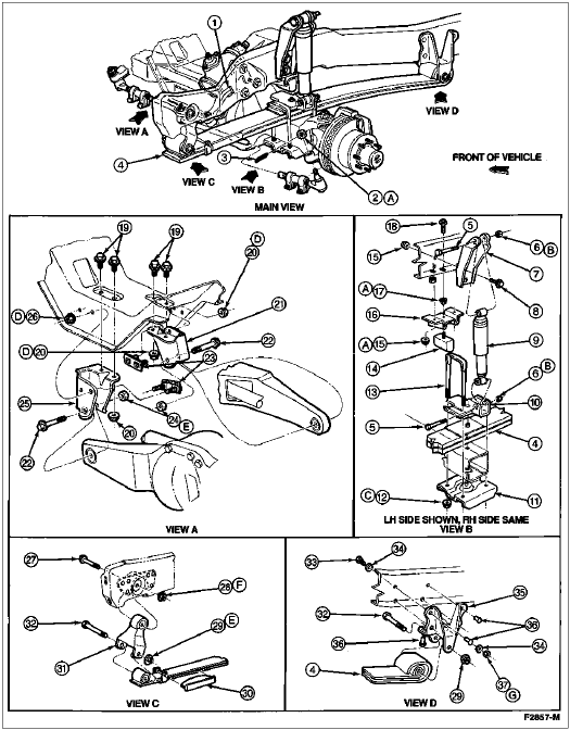
Position jack under right-hand axle assembly. Remove the two U-bolts securing the shock absorber mounting plate and front spring to axle arm.
Disconnect the vent tube at the differential housing. Remove the vent fitting and install a 3mm (1/8-inch) pipe plug or a vacuum fitting cap.
Remove and discard the keystone clamps and remove the boot from the shaft (right side).
Remove the pivot bolt that secures the right-hand axle assembly to front crossmember (5019).
Remove the right axle assembly. Pull the axle shaft out of the slip-shaft.
Position the jack under the left-hand axle assembly. Remove the two U-bolts securing the shock absorber mounting plate and front spring to tube and yoke assembly.
Position a jack under the differential housing.
Remove the pivot bolt securing the left-hand axle assembly to front crossmember. Remove the left axle assembly.

| Item | Part Number | Description |
|---|---|---|
| 1 | 3590 | Steering Gear Sector Shaft Arm |
| 2 | 800895-S56 | Nut |
| 3 | N620483-S2 | Cotter Pin |
| 4 | 5310 | Front Leaf Spring |
| 5 | N800021-S2 | Bolt |
| 6 | N806496-S301 | Nut |
| 7 | 18183 | Front Shock Absorber Mounting Bracket |
| 8 | N802114-S2 | Bolt |
| 9 | 18124 | Front Shock Absorber |
| 10 | 5458 | Front Spring Plate Spacer |
| 11 | 5A500 | U-Bolt Spacer |
| 12 | 801342-S2 | Nut |
| 13 | N805073-S56 | U-Bolt |
| 14 | 3020 | Front Suspension Bumper |
| 15 | N620483-S2 | Nut |
| 16 | 3B251 | Front Axle Bumper Bracket |
| 17 | N620482-S2 | Nut |
| 18 | N605933-S2 | Bolt |
| 19 | N802114-S2 | Bolt |
| 20 | N802073-S2 | Nut |
| 21 | 3B176 | Front Axle Pivot Bracket (RH) |
| 22 | N801079-S2 | Bolt |
| 23 | N808528-S100 | Bolt and Retainer |
| 24 | N620604-S100 | Nut |
| 25 | 3K090 | Front Axle Bearing Bracket (LH) |
| 26 | N802073-S2 | Nut |
| 27 | N601522-S2 | Bolt |
| 28 | N620485-S56 | Nut |
| 29 | N620484-S56 | Nut |
| 30 | 5L302 | Spring Insulator Sleeve |
| 31 | 5K316 | Front Spring Front Shackle |
| 32 | N800991-S2 | Bolt |
| 33 | 58634-S2 | Bolt |
| 34 | 44877-S2 | Washer |
| 35 | 5340 | Front Spring Mounting Bracket |
| 36 | N647097-S | Rivet |
| 37 | 34987-S2 | Nut |
| A | — | Tighten to 77-103 Nm (57-80 Lb-Ft) |
| B | — | Tighten to 60-80 Nm (44-59 Lb-Ft) |
| C | — | Tighten to 113-153 Nm (83-113 Lb-Ft) |
| D | — | Tighten to 88-118 Nm (65-87 Lb-Ft) |
| E | — | Tighten to 149-201 Nm (110-148 Lb-Ft) |
| F | — | Tighten to 170-230 Nm (125-170 Lb-Ft) |
| G | — | Tighten to 47-78 Nm (35-60 Lb-Ft) |
Installation
Raise vehicle on a hoist or a jack and position left axle assembly at front leaf spring. Install the pivot bolt that secures the axle assembly to the front crossmember.
Secure the shock absorber mounting plate to the front leaf spring and axle assembly with the two U-bolts. Tighten bolts to 113-153 Nm (83-113 lb-ft).
Position new keystone clamps over the grooves on the boot and crimp the clamp with Keystone Clamp Pliers T63P-9171-A.
Align the axle shaft and install in slip-shaft. Position the right-hand axle assembly at front crossmember. Install the boot on the shaft so the boot seats in the grooves. Install the pivot bolt that secures the axle assembly to front crossmember. Tighten bolt to 149-201 Nm (110-148 lb-ft).
Install shock absorber mounting plate, front leaf spring and axle assembly using two U-bolts. Tighten bolts to 113-153 Nm (83-113 lb-ft).
Install vent fitting to differential housing and connect vent tube to vent using a new hose clamp.
Connect the steering linkage. Refer to Section 11-03.
Install disc brake caliper and wheel and tire. Refer to Section 06-03.
Install front driveshaft. Refer to Section 05-01.
Install front stabilizer bar. Refer to Section 04-01B.
Check and adjust caster, camber and toe.