Section 05-03A: Axle, Front Drive, Dana Models 44 and 50 | 1996 F-150, F-250 4x4 and Bronco Workshop Manual |
Description | Tool Number |
---|---|
Keystone Clamp Pliers | T63P-9171-A |
Removal
Raise the vehicle on a hoist or jack and install safety stands under the radius arm brackets.
Remove the wheel and tire assembly and brake caliper. Refer to Section 04-04.
On vehicles equipped with four-wheel anti-lock brakes, remove the front brake anti-lock sensor (2C204) from the knuckle. Refer to Section 06-09B.
Disconnect the steering linkage from the steering knuckles. Refer to Section 11-03.
Remove front driveshaft (4602). Refer to Section 05-01.
Remove front stabilizer bar (5482). Refer to Section 04-01B.
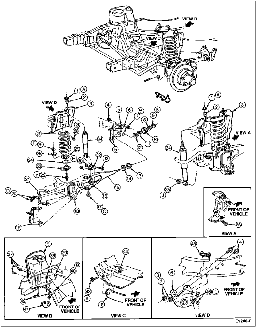
Position jack under axle arm assembly and remove the upper coil spring retainers. Remove spring lower retainer bolt. Lower the jack and remove the front coil spring (5310), spring cushion and lower spring seat.
Disconnect the front shock absorber (18124) at the radius arm and upper mounting bracket.
Remove the stud and spring seat at radius arm and axle arm. Remove bolt securing upper attachment to axle arm radius arm to lower attachment axle arm.
Disconnect the vent tube at the differential housing and discard the hose clamps. Remove the vent fitting and install a 3mm (1/8-inch) pipe plug.
Remove the pivot bolt securing the right axle arm assembly to front crossmember (5019).
Item | Part Number | Description |
---|---|---|
1 | N806246-S56 | Nut and Washer |
2 | 18198 | Shock Absorber Bushing Repair Kit |
3 | 5B315 | Front Spring Seat Upper (LH) |
4 | N802210-S | Bolt |
5 | N647096-S | Rivet |
6 | 3B183 | Radius Arm Bracket (LH) |
7 | N800937-S2 | Nut |
8 | 379572-S2 | Washer |
9 | 34992-S2 | Nut |
10 | 3B463 | Radius Arm Heat Shield |
11 | 3A184 | Outer Radius Arm |
12 | 3B244 | Spacer |
13 | 3B203 | Front Radius Arm Insulator |
14 | 3B186 | Front Radius Arm Return |
15 | 3405 | Radius Arm |
16 | N605920-S2 | Bolt |
17 | 58740-S100 | Screw |
18 | 3002 | Front Axle |
19 | 18A151 | Shock Absorber Lower Bracket (RH) |
20 | 40954-S100 | Screw |
21 | 3B446 | Axle Radius Arm Bracket |
22 | 390678-S100 | Bolt |
23 | 5A307 | Lower Spring Seat with Stabilizer Bar (RH) |
24 | 5A307 | Lower Spring Seat Without Stabilizer Bar (RH) |
25 | 5A349 | Lower Spring Return |
26 | 388833-S2 | Nut |
27 | 5A333 | Upper Spring Return |
28 | 40949-S2 | Screw |
29 | 5414 | Front Spring Insulator |
30 | N806496-S100 | Nut and Washer |
31 | N620482-S36 | Nut |
32 | 18126 | Front Shock Absorber Lower Bracket |
33 | N805033-S2 | Bolt |
34 | 18045 | Front Shock Absorber |
35 | N806085-S8 | Nut and Washer |
36 | 380288-S2 | Screw and Washer Assembly |
37 | N647096-S | Rivet |
38 | N803500-S2 | Screw |
39 | 58654-S2 | Bolt |
40 | 34988-S2 | Nut |
41 | 3020 | Front Suspension Bumper |
42 | 65095-S | Rivet |
43 | N801079-S2 | Bolt |
44 | N620604-S100 | Nut |
45 | N806727-S2 | Plate |
46 | N801670-S36 | Nut |
A | — | Tighten to 34-46 Nm (25-34 Lb-Ft) |
B | — | Tighten to 113-153 Nm (83-113 Lb-Ft) |
C | — | Tighten to 434-461 Nm (320-340 Lb-Ft) |
D | — | Tighten to 26-34 Nm (19-25 Lb-Ft) |
E | — | Tighten to 325-351 Nm (240-259 Lb-Ft) |
F | — | Tighten to 95-135 Nm (70-100 Lb-Ft) |
G | — | Tighten to 35-45 Nm (26-33 Lb-Ft) |
H | — | Tighten to 60-80 Nm (44-59 Lb-Ft) |
J | — | Tighten to 53-72 Nm (39-53 Lb-Ft) |
K | — | Tighten to 212-288 Nm (156-212 Lb-Ft) |
L | — | Tighten to 76-104 Nm (56-77 Lb-Ft) |
Remove and discard the keystone clamps and remove the boot from the shaft (right side).
Remove the right drive axle assembly and pull the axle shaft from the slip-shaft.
Position a jack under the differential housing. Remove the bolt securing the left axle assembly to the front crossmember.
Remove the left-hand drive axle.
Installation
Raise the vehicle on a hoist or a jack. Position the left drive axle assembly on a jack and position to the radius arm. Secure the left drive axle to front crossmember with the pivot bolt. Tighten bolt to 212-288 Nm (156-212 lb-ft).
Using a jack, position the right axle assembly at the front crossmember and radius arm. Install the boot on the shaft so the boot seats in the grooves.
Position new keystone clamps over the grooves on the boot and crimp the clamp with Keystone Clamp Pliers T63P-9171-A.
Align the axle shaft and install in slip-shaft. Secure right axle assembly to front crossmember with pivot bolt. Tighten to 212-288 Nm (156-212 lb-ft).
NOTE: Make sure shipping plug has been removed from vent tube. A plugged vent tube can cause leakage past seals or sealant materials.
Install vent fitting in differential housing. Connect vent tube to vent fitting using new hose clamps. Route vent hose through hole in crossmember and clip to the frame side rail.
Position spring seat and install a new upper stud at axle arm and radius arm. Tighten to 325-351 Nm (240-259 lb-ft).
Install new bolts (lower) at axle assembly and radius arm. Tighten bolts to 434-461 Nm (320-340 lb-ft).
Position front spring insulator (5414) and front coil spring on lower spring seat. Install nuts and tighten to 95-135 Nm (70-100 lb-ft).
Position jack under axle assembly and raise front coil spring into position. Install upper spring retainer and screw. Tighten to 35-45 Nm (26-33 lb-ft).
Lower the jack.
Connect front shock absorbers to upper and lower frame brackets.
On vehicles equipped with four-wheel anti-lock brakes, install the front brake anti-lock sensor on the knuckle. Refer to Section 06-09B.
Install disc brake caliper (2B120), wheel and tire.
Connect the steering linkage. Refer to Section 11-03.
Install the front stabilizer bar. Refer to Section 04-01B.
Install the front driveshaft. Refer to Section 05-01.
Lower the vehicle. Check and adjust camber and toe. Refer to Section 04-00.