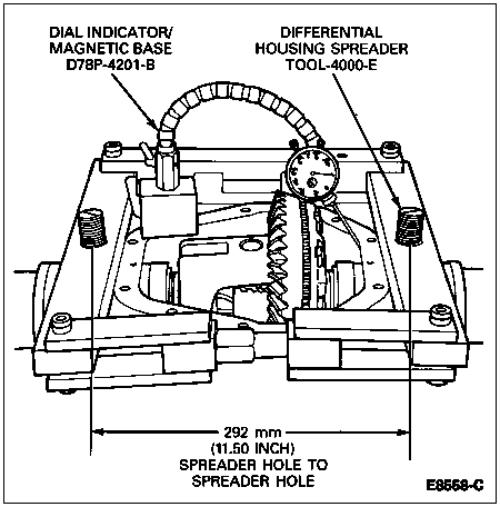
Place differential (4026) into axle housing. Differential master bearings should still be assembled to differential case (4204). Install outboard spacers in same side as removed from, when making overall measurement.
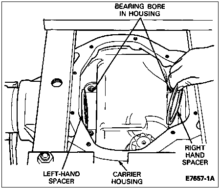
Section 05-02D: Axle, Rear, Dana | 1996 F-Super Duty Workshop Manual |
Refer to Section 05-02E for adjustment of rear wheel bearings and specific adjustments of rear hubs (1109).
Refer to Section 06-04 for rear disc brake assembly and disassembly procedures.
Place differential (4026) into axle housing. Differential master bearings should still be assembled to differential case (4204). Install outboard spacers in same side as removed from, when making overall measurement.

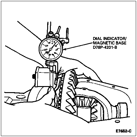
Set up dial indicator as shown. Locate dial indicator on a flat surface of one of the ring gear and pinion screws.
Force the differential case assembly (ring gear) away from the pinion gear. With force still applied to the differential case set indicator at zero.
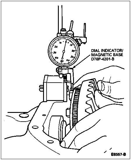
NOTE: Repeat the following step until the same reading is obtained each time. This reading will be the necessary amount of pinion shims required between the differential case and differential bearings (4221) on the ring gear and pinion side.
Force the differential case assembly (ring gear) into mesh with the pinion gear to obtain an indicator reading.
Remove indicator and differential case from the carrier.
Remove master bearings from differential case.
As determined in the measurement obtained under Differential Case End Play Check earlier in this section, place the required amount of shims on the ring gear hub of the differential case. For example, if the reading was 1.14mm (0.045 inch), place 1.14mm (0.045 inch) of shim on the hub of the ring gear side of the differential case.
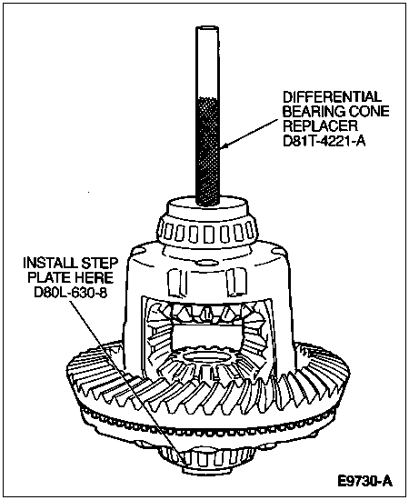
Install the bearing cone on the ring gear side of the differential case. Drive the bearing onto the hub using Differential Bearing Cone Replacer D81T-4221-A or equivalent.
To determine the correct amount of shims to be placed on the hub of the drive pinion side of the differential case, subtract the reading obtained in this procedure from the Total Differential Case End Play. Total Case End Play was determined under Differential Case End Play Check. When this amount is determined, add 0.25mm (0.010 inch). This is the required amount of shims to be placed on the hub of the drive pinion side of the differential case.
For example, Total Differential Case End Play was 2.30mm (0.091 inch). The reading in Step 7 was 1.14mm (0.045 inch), and when subtracted from 2.30mm (0.091 inch) gives 1.16mm (0.046 inch). 0.25mm (0.010 inch) is added to give 1.41mm (0.056 inch) amount of pinion shims to be placed on the hub of the drive pinion side of the differential case.
Install required amount of pinion shims on the hub of the drive pinion side of the differential case.
Install the bearing cone on the hub of the drive pinion side of the differential case. Place Step Plate D80L-630-8 or equivalent on the ring gear side bearing to protect the bearing during installation of the drive pinion side bearing.
Drive the bearing onto the drive pinion side hub using Differential Bearing Cone Replacer D81T-4221-A or equivalent.
![]() CAUTION: Do not spread rear axle differential carrier (4141) over 0.38mm (0.015 inch).
CAUTION: Do not spread rear axle differential carrier (4141) over 0.38mm (0.015 inch).
Install Differential Housing Spreader TOOL-4000-E and Dial Indicator/Magnetic Base D78P-4201-B or equivalents to carrier. Do not spread carrier over 0.38mm (0.015 inch). Remove indicator.
