Section 05-02D: Axle, Rear, Dana | 1996 F-Super Duty Workshop Manual |
DISASSEMBLY AND ASSEMBLY
Axle Assembly
Differential Case Assembly
Place differential case (4204) in vise. Apply Premium Long-Life Grease XG-1-C or -K or equivalent meeting Ford specification ESA-M1C75-B to new differential side gear thrust washers (4228) and to rear hubs (1109) and thrust face of the new differential side gears (4236).
Install both differential side gears. Apply grease to the new differential pinion thrust washers (4230) and the new differential pinion gears (4215).
NOTE: An easy way to assemble the differential side gears and differential pinion gears is to have all parts lubricated with rear axle lubricant meeting Ford specification WSP-M2C197-A before assembly.
Assemble both differential side gears and differential side gear thrust washers, hold in place with hand, then assemble the differential pinion gears and differential pinion thrust washers to hold the differential side gears in place.
Rotate the differential side gears until the holes of the washers and differential pinion gears line up with the holes of the differential case. If the differential pinion gears cannot be rotated by hand, install one of the axle shafts (4234) into the spline ofdifferential side gear and use a pipe wrench to turn the axle shaft.

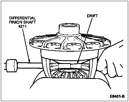
Use a drift to line up the holes with those of the differential case.
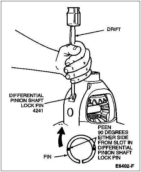
Assemble drive pinion shaft and drive on differential pinion shaft (4211) to remove drift. Align differential pinion shaft lock pin hole of the differential pinion shaft with the differential pinion shaft lock pin hole of the differential case.
Assemble differential pinion shaft lock pin (4241). Peen metal of differential case over pin in two places 180 degrees apart to lock in place. Note the location of the slot in the differential pinion shaft lock pin and peen 90 degrees away.
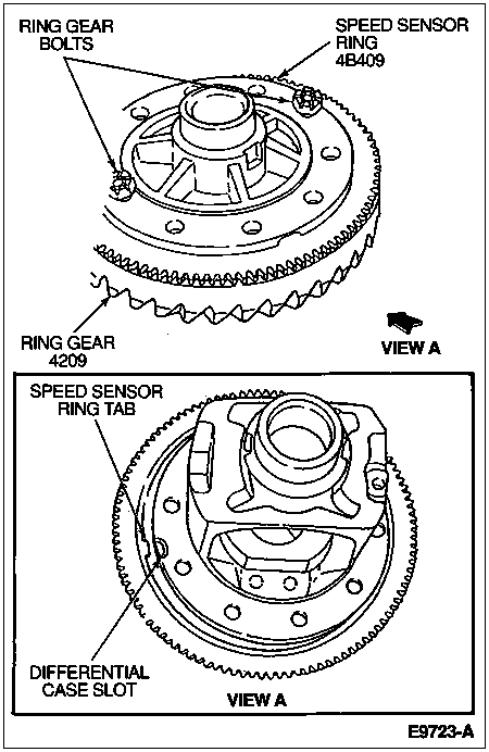
 CAUTION: Tab on speed sensor ring must be aligned with slot in differential case.
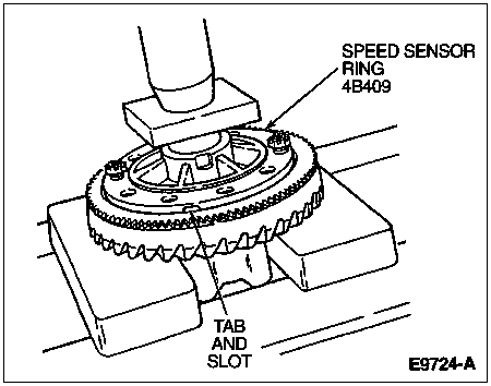
Align tab in speed sensor ring with slot in differential case. Start two ring gear bolts through the differential case into the ring gear to make sure differential case and ring gear bolt hole align.
Press the speed sensor ring on the differential case. The differential case flange acts as a pilot for the speed sensor ring. Apply Thread Lock and Sealer EOAZ-19554-AA or equivalent meeting Ford specification WSK-M2G315-A5 (TYPE II) to new ring gear bolts.
Draw up ring gear bolts alternately and evenly. Tighten ring gear bolts to 272-325 Nm (200-240 lb-ft).
Differential Case End Play Check
Install Master Bearings Set D81T-4222-E or equivalent to differential case.
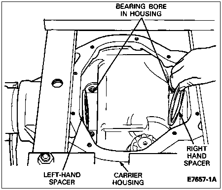
Remove all nicks, burrs, dirt, etc., from differential case bearing hubs and rear axle differential carrier (4141) to allow bearings to rotate freely.
Install outboard differential spacers into rear axle differential carrier. Assemble differential case into carrier (less pinion).
NOTE: Dial indicator should have a minimum travel capability of 5.08mm (0.200 inch).
Mount Dial Indicator/Magnetic Base D78P-4201-B or equivalent as shown. Locate tip of indicator on flat surface of one of the ring gear screw spot faces.
NOTE: Repeat the following steps until you have obtained the same reading. Record the reading of the indicator. This will be the total amount of differential bearing shims (4067) required (less preload) and will be calculated later during assembly.
Force differential (4026) as far as possible in the direction toward the indicator. With force still applied, set indicator at zero (0).
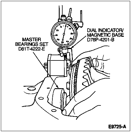
Force the differential as far as it will go in the opposite direction.
After making sure the readings are correct, remove indicator and differential from rear axle housing (4010). DO NOT REMOVE MASTER BEARINGS FROM DIFFERENTIAL CASE AT THIS TIME.
This reading is the Total Differential Case End Play which will be needed for Assembly of Differential into Housing in this section.
Pinion Ring Gear Variation Number
NOTE: If baffle or rear axle drive pinion shaft oil slinger (4670) is bent or mutilated, it should be replaced.
Ring gears and pinions are supplied in matched sets only. Matching numbers on both the pinion and ring gear are etched for verification. If a new ring gear and pinion is being used, verify the numbers of each pinion and ring gear before proceeding with assembly. The end of the pinion with the etched figures shown is known as the "button" end.
Use the gear contact pattern method to make sure the final pinion position is valid.
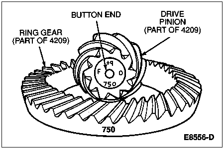
On the button end of each pinion, there is etched a plus (+) number, a minus (-) number, or a zero (0) number which indicates the best running position for each particular ring gear. This dimension is controlled by the shimming behind the inner pinion bearing cup (the backface).
The distance from the centerline of the ring gear to the backface of the pinion is 147.6mm (5.812 inches).

| Item | Part Number | Description |
| 1 | � | Tooth Combination Stamped Here |
| 2 | 4663 | Drive Pinion Bearing Adjustment Shims |
| 3 | � | Button End (Part of 4209) |
| 4 | � | Centerline of Differential Ring Gear and Pinion |
| 5 | 4670 | Rear Axle Drive Pinion Shaft Oil Slinger |
| 6 | � | Pinion Oil Baffle |
| A | � | 148mm |
For example, if a pinion is etched m+8 (+3), this pinion would require 0.08mm (0.003 inch) less drive pinion shims than a pinion etched "0." This means by removing drive pinion shims, the mounting distance of the pinion is increased, which is just what an m+8 (+3) indicates. Or if a pinion is etched m-8 (-3), we would add 0.08mm (0.003 inch) more shims than would be required if the pinion were etched "0." By adding 0.08mm (0.003 inch) pinion shims, the mounting distance of the pinion was decreased, which is just what an m-8 (-3) indicated.
If the old ring gear and pinion is to be reused, measure the old pinion shims and build a new pack of pinion shims to this same dimension. If a baffle is used in the rear axle assembly (4006), it is considered part of the shim pack.
To change the pinion adjustment, pinion shims are available in thicknesses of 0.08, 0.13 and 0.25mm (0.003, 0.005 and 0.010 inch).
Measure each shim separately with a micrometer and add together to get the total shim pack thickness from the original buildup.
If a new ring gear and pinion is being used, notice the (+) or (-) etching on both the old and new pinion and adjust the thickness of the new shim pack to compensate for the difference of these two figures.
For example, if the old pinion reads m+5 (+2) and the new is m-5 (-2), add 0.10mm (0.004 inch) pinion shims to the original shim pack.
| Old Pinion Marking | New Pinion Marking (English) |
|---|
| -4 | -3 | -2 | -1 | 0 | +1 | +2 | +3 | +4 |
|---|
| +4 | +0.008 | +0.007 | +0.006 | +0.005 | +0.004 | +0.003 | +0.002 | +0.001 | 0 |
| +3 | +0.007 | +0.006 | +0.005 | +0.004 | +0.003 | +0.002 | +0.001 | 0 | -0.001 |
| +2 | +0.006 | +0.005 | +0.004 | +0.003 | +0.002 | +0.001 | 0 | -0.001 | -0.002 |
| +1 | +0.005 | +0.004 | +0.003 | +0.002 | +0.001 | 0 | -0.001 | -0.002 | -0.003 |
| 0 | +0.004 | +0.003 | +0.002 | +0.001 | 0 | -0.001 | -0.002 | -0.003 | -0.004 |
| -1 | +0.003 | +0.002 | +0.001 | 0 | -0.001 | -0.002 | -0.003 | -0.004 | -0.005 |
| -2 | +0.002 | +0.001 | 0 | -0.001 | -0.002 | -0.003 | -0.004 | -0.005 | -0.006 |
| -3 | +0.001 | 0 | -0.001 | -0.002 | -0.003 | -0.004 | -0.005 | -0.006 | -0.007 |
| -4 | 0 | -0.001 | -0.002 | -0.003 | -0.004 | -0.005 | -0.006 | -0.007 | -0.008 |
| Old Pinion Marking | New Pinion Marking (Metric) |
|---|
| -10 | -8 | -5 | -3 | 0 | +3 | +5 | +8 | +10 |
|---|
| +10 | +.20 | +.18 | +.15 | +.13 | +.10 | +.08 | +.05 | +.03 | 0 |
| +8 | +.18 | +.15 | +.13 | +.10 | +.08 | +.05 | +.03 | 0 | -.03 |
| +5 | +.15 | +.13 | +.10 | +.08 | +.05 | +.03 | 0 | -.03 | -.05 |
| +3 | +.13 | +.10 | +.08 | +.05 | +.03 | 0 | -.03 | -.05 | -.08 |
| 0 | +.10 | +.08 | +.05 | +.03 | 0 | -.03 | -.05 | -.08 | -.10 |
| -3 | +.08 | +.05 | +.03 | 0 | -.03 | -.05 | -.08 | -.10 | -.13 |
| -5 | +.05 | +.03 | 0 | -.03 | -.05 | -.08 | -.10 | -.13 | -.15 |
| -8 | +.03 | 0 | -.03 | -.05 | -.08 | -.10 | -.13 | -.15 | -.18 |
| -10 | 0 | -.03 | -.05 | -.08 | -.10 | -.13 | -.15 | -.18 | -.20 |
Pinion Bearing Cup Installation
SPECIAL SERVICE TOOL(S) REQUIRED
| Description | Tool Number |
|---|
| Pinion Bearing Cup Replacer | T67P-4616-A |
| Threaded Drawbar | T75T-1176-A |
| Axle Bearing/Seal Plate | T75L-1165-B |
| Companion Flange Holding Tool | T57T-4851-B |
| Companion Flange Remover | T65L-4851-B |
| Pinion Oil Seal Replacer | T88T-4676-A |
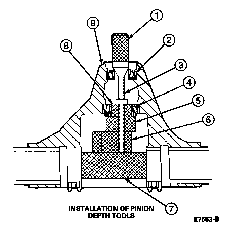
Place the inner and outer differential bearing cups into the carrier bore.
Place the inner bearing cup replacer tool on the inner differential drive pinion bearing cup (4616). Use Pinion Bearing Cup Replacer D81T-4616-A or equivalent.
Place the outer bearing cup replacer tool on the outer differential drive pinion bearing cup. Use Pinion Bearing Cup Replacer T67P-4616-A.
Install the Threaded Drawbar T75T-1176-A into the replacer tools and tighten the drawbar to install the differential drive pinion bearing cups into the carrier bore.
| Item | Part Number | Description |
| 1 | 4616 | Differential Drive Pinion Bearing Cup (Inner) |
| 2 | T67P-4616-A | Pinion Bearing Cup Replacer |
| 3 | T75T-1176-A | Threaded Draw Bar |
| 4 | 4616 | Differential Drive Pinion Bearing Cup (Outer) |
| 5 | D81T-4616-A | Pinion Bearing Cup Replacer |
| A | � | Outer Cup Installation View |
| B | � | Inner Cup Installation View |
Pinion Position Shim Selection
NOTE: If any of the gauge surfaces become nicked, the high spots must be removed with a medium India oilstone to make sure there are no erroneous readings.
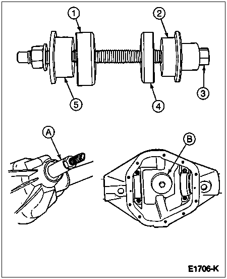
Place a new inner drive pinion bearing cone over the proper aligning adapter and insert into the axle carrier bore.
The 3/8-inch square drive in the handle to be used for obtaining the proper pinion bearing preload and tighten to preload of 2.26-4.53 Nm (20-40 lb-in).
Place the outer drive pinion bearing cone (new or used if in good condition) into the differential drive pinion bearing cup and assemble the handle onto the screw and hand tighten.
| Item | Part Number | Description |
| 1 | T88T-4020-B | Handle |
| 2 | 4630 | Differential Pinion Bearing |
| 3 | T80T-4020-F43 | Screw |
| 4 | 4621 | Differential Pinion Bearing |
| 5 | T88T-4020-A | Gauge Disc |
| 6 | T80T-4020-F42 | Gauge Block |
| 7 | D81T-4020-F51 | Gauge Tube |
| 8 | D80T-4020-R60 | Aligning Adapter |
| 9 | 4010 | Rear Axle Housing |
Center the proper gauge tube into the differential bearing bore. Install the bearing caps and tighten to 95-122 Nm (70-90 lb-ft).
Make sure the shims or feeler gauges are free of dirt to prevent an incorrect reading.
NOTE: The feeler gauge fit between the gauge tube and the gauge block should have a slight drag-type feeling.
Using a feeler gauge tool or shims, select the thickest feeler shim that will enter between the gauge tube and the gauge block. Insert the feeler gauge directly along the gauge block so a correct reading can be made.
NOTE: If the service pinion gear is marked with a plus (+) reading, this amount must be subtracted from the thickness dimension obtained between gauge block and gauge tube.
NOTE: If the service pinion gear is marked with a minus (-) reading, this amount must be added to the thickness dimension obtained between gauge block and gauge tube.
NOTE: In addition you must use the exact same new inner pinion bearing used in the previous steps.
After the correct feeler gauge feel is obtained, check the reading. This is the thickness of pinion shims required providing that, upon inspection of the service pinion gear, there are no markings.
CAUTION: The drive pinion preload spacer and pinion shim assembly sequence must be followed. If sequence is not followed and components are improperly assembled, it may cause unit failure. If pinion shims are damaged, replace with new ones. Shims are available in the thicknesses shown in the following chart.
NOTE: If a baffle or rear axle drive pinion shaft oil slinger is used, replace with a new one upon assembly and measure as part of the shim stack.
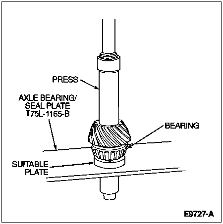
Remove the inner differential drive pinion bearing cup and install the correct thickness of pinion shims in the carrier bore. Reinstall the differential drive pinion bearing cup and baffle (if used). Install rear axle drive pinion shaft oil slinger if an rear axle drive pinion shaft oil slinger is used, between the pinion gear head and inner pinion bearing cone. Assemble onto the pinion shaft and press on the cone with Axle Bearing/Seal Plate T75L-1165-B and a suitable plate which contacts the bearing cone.
PINION SHIMS
| mm | Inches |
|---|
| .36 | .014 |
| .38 | .015 |
| .41 | .016 |
| .46 | .018 |
| .51 | .020 |
| .53 | .021 |
| .56 | .022 |
| .58 | .023 |
| .76 | .030 |
After following these procedures, continue to build the remaining components with proper pinion and differential bearing preload torques and differential ring gear and pinion backlash.
Assemble pinion shims onto pinion and install pinion gear into rear axle housing. Assemble outer bearing cone and roller assembly onto pinion.
Assemble rear axle universal joint flange (4851), washer and new pinion nut on the pinion shaft. Tighten nut to 597-677 Nm (440-500 lb-ft).
Using a pound-inch torque wrench, rotate pinion. Torque to rotate pinion should read 2.26-4.53 Nm (20-40 lb-in). To increase preload, remove pinion shims from the outer shim pack. To decrease preload, add shims.
The direction pointing toward the companion flange indicates that by removing shims, the distance from the centerline of the tubes to pinion backface is increased, giving a plus (+) reading. The differential pinion bearing preload shim pack does not affect the pinion depth setting. However, if pinion position is changed, the pinion preload will change and may require adjustment to bring torque-to-rotation within specification. Arrows on the ring gear illustrate the method to increase or decrease backlash and differential bearing preload.
If pinion bearing preload is within specification and the pinion position is changed, the drive pinion bearing adjustment shims (4663) should be changed by the same amount.
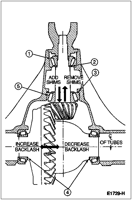
| Item | Part Number | Description |
| 1 | 4630 | Differential Pinion Bearing, Outer |
| 2 | 4663 | Outer Drive Pinion Bearing Adjustment Shims (Preload) |
| 3 | 4663 | Inner Drive Pinion Bearing Adjustment Shims (Position) |
| 4 | 4067 | Differential Bearing Shims |
| 5 | 4621 | Differential Pinion Bearing, Inner |
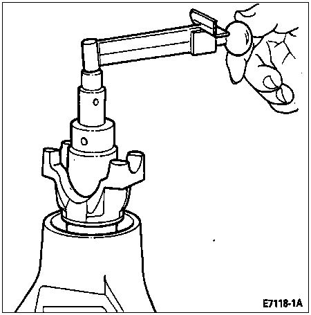
With the drive pinion at the correct preload as determined earlier in this procedure, remove the pinion nut, drive pinion nut locking washer with Companion Flange Holding Tool T57T-4851-B and Companion Flange Remover T65L-4851-B.
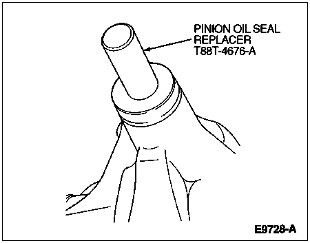
Coat the rear axle drive pinion seal (4676) with grease. Install the pinion seal with Pinion Oil Seal Replacer T88T-4676-A. After installation, make sure the garter spring did not pop out. If the garter spring pops out, remove and replace rear axle drive pinion seal.
Install the rear axle universal joint flange using Companion Flange Replacer T88T-4851-A.
NOTE: Whenever the rear axle universal joint flange is removed, the pinion washer and pinion nut should be replaced.
Install the washer and nut and tighten nut to 597-677 Nm (440-500 lb-ft).
