Section 05-01: Driveshaft | 1996 F-150, F-250, F-350 4x2, 4x4, F-Super Duty Chassis Cab, Motorhome Chassis and Bronco Vehicles Workshop Manual |
Description | Tool Number |
---|---|
U-Joint Tool | T74P-4635C |
Disassembly
CAUTION: Under no circumstances is the driveshaft to be clamped in the jaws of a
vise or similar holding fixture. Denting or localized fracture of the tube may result, which may cause driveshaft failure during vehicle operation.
Place the driveshaft (4602) on a suitable workbench being careful not to damage the tube.
Mark the positions of the spiders, the driveshaft center yoke (4784), and the driveshaft centering socket yoke (4782) as related to the stud yoke that is welded to the front of the driveshaft.
Remove the snap rings that secure the bearings in the front of the driveshaft center yoke.
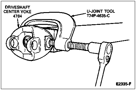
Position U-Joint Tool T74P-4635-C as shown. Tighten the tool clockwise until the bearing protrudes approximately 9.525mm (3/8 inch) out of the yoke.
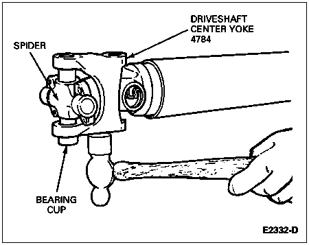
Clamp the bearing in a vise and tap on the driveshaft center yoke to free it from the bearing.
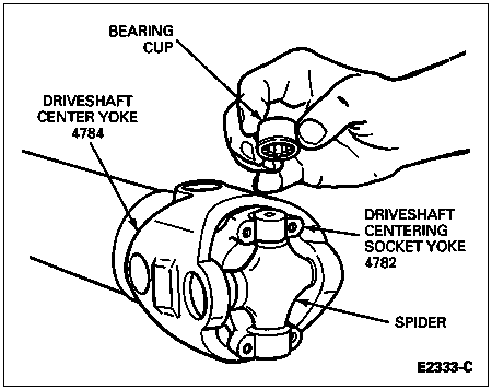
Lift the two bearing cups from the spider.
Reposition the tool on the driveshaft center yoke and move the remaining bearing in the opposite direction so that it protrudes approximately 9.525mm (3/8 inch) out of the driveshaft center yoke.
Clamp the bearing in a vise. Tap on the driveshaft center yoke to free it from the bearing.
Remove the spider from the driveshaft center yoke.
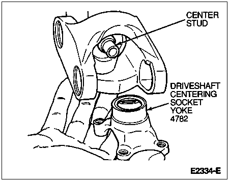
Pull the driveshaft centering socket yoke off the center stud. Remove the rubber seal from the centering ball stud.
Remove the snap rings from the driveshaft center yoke and from the driveshaft yoke.
Position the U-joint tool on the driveshaft yoke and press the bearing outward until the inside of the driveshaft center yoke almost contacts the oil slinger at the front of the driveshaft yoke.
Pressing beyond this point can distort the oil slinger. The following illustration shows the interference point.
Clamp the exposed end of the bearing in a vise and drive on the driveshaft center yoke with a soft-faced hammer to free it from the bearing.
Reposition the tool and press on the spider to remove the opposite bearing.
Remove the driveshaft center yoke from the spider.
Remove the spider from the driveshaft yoke in the same manner.
Clean all serviceable parts in cleaning solvent. If using a repair kit, install all of the parts supplied in the kit. If the driveshaft is damaged, replace the complete shaft to be assured of a balanced assembly.
Assembly
NOTE: Universal joint kits are to be installed as complete assemblies only. Do not mix any components from other universal joint kits.
Position the spider in the driveshaft yoke. Make sure the spider bosses (or lubrication plugs on kits) will be in the same position as originally installed.
Press in the bearing using U-Joint Tool T74P-4635-C. Install the snap rings.
Pack the socket relief and the ball with Premium Long-Life Grease XG-1-C or -K or equivalent meeting Ford specification ESA-M1C75-B.
Position the driveshaft center yoke over the spider ends and press in the bearing. Install the snap rings.
Install a new seal on the centering ball stud. Position the driveshaft centering socket yoke on the stud.
Place the front spider in the driveshaft center yoke. Make sure the spider bosses are properly positioned.
With the spider loosely positioned on driveshaft center yoke, proceed to seat the first pair of bearings into the driveshaft centering socket yoke, then press the second pair into the driveshaft center yoke. Install the snap rings.
Apply pressure on the driveshaft centering socket yoke and install the remaining bearing cup.
Lubricate the universal joint (if equipped with grease fittings) with Premium Long-Life Grease XG-1-C or -K or equivalent meeting Ford specification ESA-M1C75-B.