Section 05-01: Driveshaft | 1996 F-150, F-250, F-350 4x2, 4x4, F-Super Duty Chassis Cab, Motorhome Chassis and Bronco Vehicles Workshop Manual |
Description | Tool Number |
---|---|
U-Joint Tool | T74P-4635-C |
Disassembly
CAUTION: Under no circumstances is the driveshaft to be clamped in the jaws of a vise or similar holding fixture. Denting or localized fracture of the tube may result, which may cause driveshaft and coupling shaft failure during vehicle operation.
Place the driveshaft on a suitable workbench, being careful not to damage the tube.
NOTE: If components are not marked and therefore installed incorrectly, driveline imbalance may occur.
Prior to disassembly, mark the positions of the driveshaft components relative to the driveshaft tube. All components must be reassembled in the same relationship to maintain proper balance.
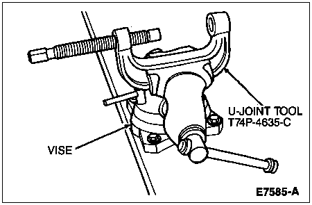
Clamp U-Joint Tool T74P-4635-C in vise.
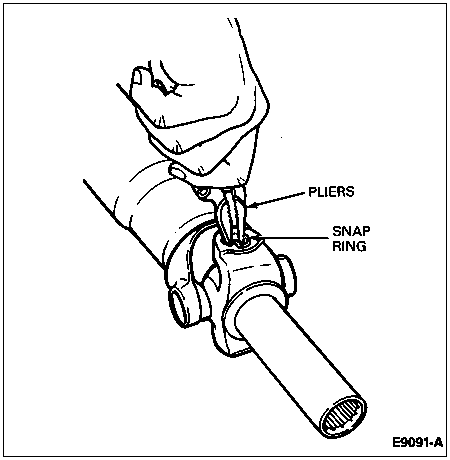
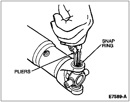
Remove the snap rings that retain the bearing cups.
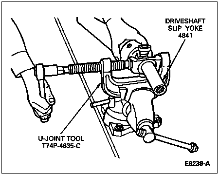
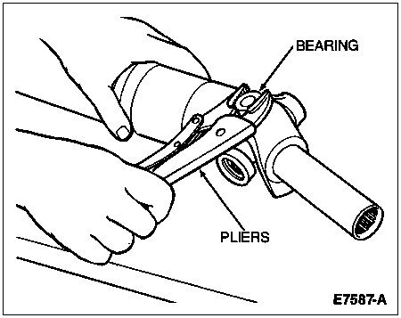
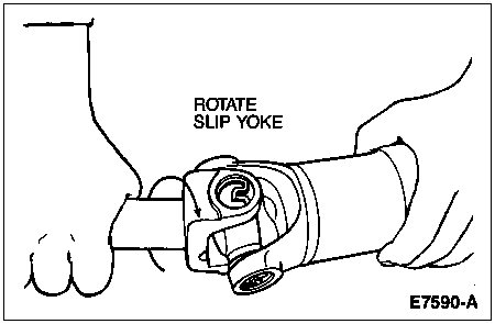
Position the driveshaft slip yoke (4841) in the U-Joint Tool and press out bearing. If bearing cup cannot be pressed all the way out of the driveshaft slip yoke, remove it with vise grip or channel lock pliers.
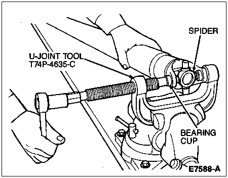
Reposition the driveshaft slip yoke in U-Joint Tool 180 degrees from previous position. Press on the spider and remove the remaining bearing cup from the opposite side.
Remove driveshaft slip yoke from the spider.
Remove the remaining bearing cups, spiders and driveshaft flange yoke (4866) from the driveshaft (4602) in the same manner.
Clean all foreign matter from the yoke area at each end of the driveshaft.
Assembly
NOTE: Universal joint kits are to be installed as complete assemblies only. Do not mix components from other universal joints.
Start a new bearing cup into the driveshaft yoke.
Position the new spider in the driveshaft yoke and press the bearing cup 6.3mm (1/4 inch) below the yoke surface using U-Joint Tool T74P-4635-C.
Remove driveshaft from U-joint tool and install a new snap ring.
Start a new bearing cup into the opposite side of the yoke. Check needles for proper position.
Position driveshaft in U-joint tool and press on the bearing cup until the opposite bearing cup contacts the snap ring.
NOTE: Assemble universal joint using the yellow snap rings supplied in the kit. If difficulty is encountered with yellow snap rings, install the black snap rings supplied in the kit.
Remove the driveshaft from tool and install a new snap ring. Check snap ring for proper seating.
Install the remaining new bearing cups, spider, driveshaft slip yoke, driveshaft flange yoke and snap rings in the same manner.
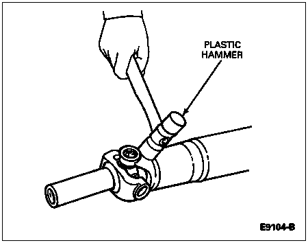
Check U-joints for freedom of movement. The effort required for movement should not exceed 4 Nm (35 lb-in) when measured with a spring scale. If binding has resulted from misalignment during assembly, a sharp rap on the yokes with a brass or plastic hammer will seat bearing needles. Take care to support the shaft end and do not strike the bearings during this procedure. Make sure U-joints rotate easily without binding before installing driveshaft.
Lubricate the universal joints (if equipped with grease fittings) with Premium Long-Life Grease XG-1-C or -K or equivalent meeting Ford specification ESA-M1C75-B.