Section 03-06: Starting System | 1996 F-Series and Bronco Workshop Manual |
The function of the starting system is to crank the engine (6007) at a speed fast enough to permit the engine to start.
![]() WARNING: WHEN SERVICING THE STARTER MOTOR OR PERFORMING OTHER UNDERHOOD WORK IN THE VICINITY OF THE STARTER MOTOR, BE AWARE THAT THE HEAVY-GAUGE BATTERY INPUT LEAD AT THE STARTER SOLENOID IS ELECTRICALLY HOT AT ALL TIMES.
WARNING: WHEN SERVICING THE STARTER MOTOR OR PERFORMING OTHER UNDERHOOD WORK IN THE VICINITY OF THE STARTER MOTOR, BE AWARE THAT THE HEAVY-GAUGE BATTERY INPUT LEAD AT THE STARTER SOLENOID IS ELECTRICALLY HOT AT ALL TIMES.
The system consists of the following components:
Starter System
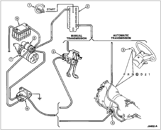
| Item | Part Number | Description |
|---|---|---|
| 1 | 3F532 | Key Release Lever Spring |
| 2 | 11572 | Ignition Switch |
| 3 | 7210 | Gearshift Lever |
| 4 | 7A247 | Park/Neutral Position Switch |
| 5 | 11A152 | Clutch Pedal Position Switch |
| 6 | 11450 | Starter Motor Solenoid Relay Switch |
| 7 | 11001 | Starter Motor |
| 8 | 11390 | Starter Solenoid |
| 9 | 10655 | Battery |
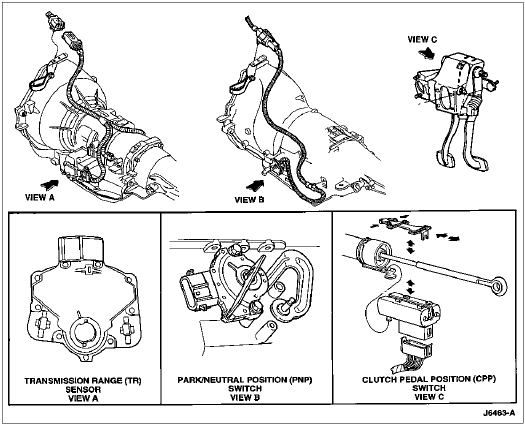
Transmission Range (TR) Sensor
The electronic E400 and 4R70W transmissions are equipped with a transmission range (TR) sensor. In addition to providing the powertrain control module (PCM) (12A650) with manual lever position (P R N OD D 2 1) signals, the sensor provides a neutral safety switch function. The circuit to the starter motor solenoid relay switch is interrupted in all gearshift lever (7210) positions except park and neutral.
Park/Neutral Position (PNP) Switch
The nonelectronic C6 transmission is equipped with a park/neutral position switch. The circuit to starter motor solenoid relay switch is completed by the PNP switch when the transmission manual lever is in park or neutral.
Clutch Pedal Position Switch
On a manual transmission-equipped vehicle, starter motor operation is prevented by a clutch pedal position switch. When the clutch pedal (7519) is pressed, the switch completes the circuit between the ignition switch and the starter motor solenoid relay switch.
Neutral Safety Switches
Starter Motor
The gasoline and diesel engine starter motors are of the same basic construction and function essentially the same. Electrically, both motors consist of an armature, field coils and a brush assembly.
The field coils are mounted in the starter frame and are held in position by the pole shoes. Current flow through field coils generates magnetic fields that are concentrated by the pole shoes.
The armature consists of insulated wire loops connected to the segments on the commutator. Battery current supplied to the armature wires through the brushes and commutator generates magnetic fields in the armature. The repelling action between the magnetism generated in the armature loops and field coils forces the armature to rotate. The rotating armature is supported on bronze bushings located in the brush end housing and drive end housing.
In both starters, the armature operates through a planetary gearset. The end of the armature serves as the drive member or sun gear. The planetary gears, driven by the armature, are mounted on pins attached to the output shaft. The stationary member, or internal gear, is anchored to the motor frame. As the armature rotates, it drives the planetaries and output shaft around the internal gear. The gear reduction through the planetaries allows for a smaller starter with adequate torque to crank the engine.
Starter Motor Geartrain, Gasoline
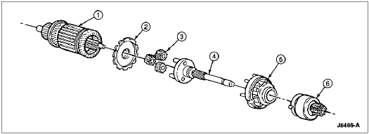
| Item | Part Number | Description |
|---|---|---|
| 1 | 11005 | Armature (Sun Gear) |
| 2 | 11A167 | Retainer |
| 3 | 11K190 | Planetary Pinion Gears |
| 4 | 11A160 | Output Shaft |
| 5 | 11A165 | Stationary (Internal Gear) |
| 6 | 11350 | Starter Drive |
Starter Motor Geartrain, Diesel
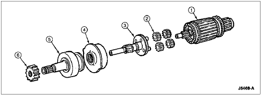
| Item | Part Number | Description |
|---|---|---|
| 1 | 11005 | Armature (Sun Gear) |
| 2 | 11K190 | Planetary Pinion Gears |
| 3 | 11355 | Output Shaft |
| 4 | 11A165 | Stationary (Internal Gear) |
| 5 | 11350 | Starter Drive |
| 6 | 11363 | Pinion Gear |
Starter Solenoid
The starter solenoid (11390) performs two functions. It shifts the starter drive pinion into engagement with the flywheel ring gear and connects the starter motor to the positive side of the battery.
The drive pinion is shifted through a lever which is connected to the solenoid plunger. The electrical circuit between the starter B and M terminals is closed by a contact disc which is also attached to the solenoid plunger.
Movement of the plunger is the result of a magnetic field generated by the pull-in and hold-in windings contained in the solenoid.
When the key is turned to START, current flows through both solenoid windings. This creates a magnetic field strong enough to pull in the plunger, shifting the overrunning clutch and drive pinion into mesh with the flywheel ring gear. As the plunger nears bottom it strikes the contact disc and forces the disc against the starting motor contacts. This completes the battery circuit, and the starting motor operates.
When the contact disc closes the contacts, the pull-in winding loses its effect due to the voltage being equal at both ends of the winding. The hold-in coil continues to hold the plunger in the closed position and reduces the current needed by the solenoid. When the ignition switch is released, the current to the solenoid stops. The springs within the solenoid open the starting motor circuit contacts and shift the clutch and pinion assembly to the at-rest position.

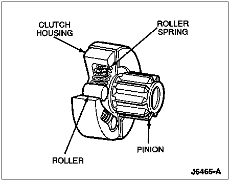
Overrunning Clutch
During engine cranking, the drive pinion is locked to the output shaft through an overrunning clutch. When the engine starts and picks up speed, the overrunning clutch allows the pinion to spin freely on the cranking motor driveshaft, preventing the engine from driving the cranking motor. This protects the armature from excessive speed during the brief period that the starter drive pinion gear remains enmeshed and the engine has started.
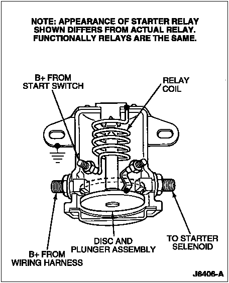
Starter Relay
The starter motor solenoid relay switch is an electrically operated switch used to connect the windings in the starter motor solenoid to the battery. The relay consists of a coil, plunger and contact disc. When the coil is connected to battery power through the ignition switch, it becomes an electromagnet. The magnetic force draws the plunger into the coil core. A disc connected to the plunger contacts the relay terminal, completing the battery to solenoid circuit. When the key or button is released, the magnetic field in the coil collapses and spring pressure returns the plunger and contact disc to the open circuit position.
