Section 03-04B: Fuel Charging and Controls, 5.0L and 5.8L Engines
1996 Vehicles Equipped with 5.0L and 5.8L SFI V-8 Engines Workshop Manual
REMOVAL AND INSTALLATION

Fuel Injection Supply Manifold

 
SPECIAL SERVICE TOOL(S) REQUIRED
DescriptionTool Number
Spring Lock Coupling Disconnect ToolT81P-19623-G1
Spring Lock Coupling Disconnect ToolT81P-19623-G2

Removal

  1. Perform Pre-Service procedures as described in Fuel Charging System in the Removal and Installation portion of this section.

  1. Remove upper intake manifold (9424). Refer to Section 03-01B.

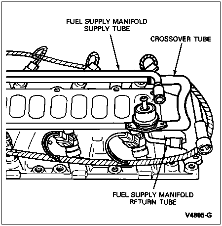
  1. Disconnect fuel supply and return tube retaining clips.

  1.  WARNING: RELIEVE FUEL SYSTEM PRESSURE BEFORE DISCONNECTING COUPLING.

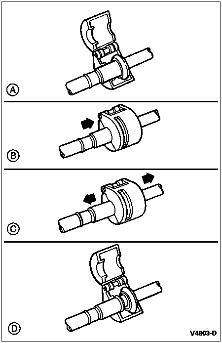
    Using Spring Lock Coupling Disconnect Tool T81P-19623-G1 (3/8 Inch) or T81P-19623-G2 (1/2 Inch), disconnect the fuel chassis inlet and outlet fuel tubes from the fuel injection supply manifold (9F792) as follows:

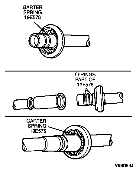
    1. Fit tool to coupling so that tool can enter cage opening to release the garter spring.
    1. Push the tool into the cage opening to release the female fitting from the garter spring.
    1. Pull the coupling male and female fittings apart.
    1. Remove the tool from the disconnected coupling.
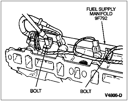
  1. Remove four (two per group) fuel injection supply manifold retaining bolts.


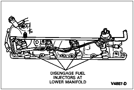
  1. NOTE: Fuel injectors (9F593) will stay in fuel injection supply manifold when removed.

    Remove fuel injection supply manifold.

Installation

  1. Make sure fuel injector end caps are clean and free of contamination.

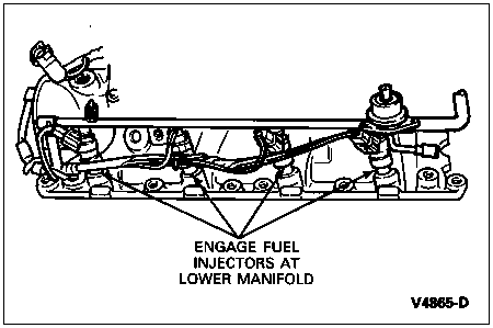
  1. Install fuel injectors into fuel injection supply manifold, then seat fuel injectors into pockets in lower intake manifold. Make sure the fuel injectors are properly seated.

  1. Secure the fuel injection supply manifold using four retaining bolts. Tighten to 8-12 Nm (70-105 lb-in).

  1. Connect the fuel inlet and outlet tubes at the fuel injection supply manifold connections as follows:

    1. Check for missing or damaged garter spring, remove damaged spring with small hooked wire, and install new spring.
    1. Clean fittings with solvent. Check for missing or damaged O-rings. Replace missing O-rings. If either O-ring is damaged, replace both.
    1. Assemble fitting by pushing with a slight twisting motion.
    1. To check coupling engagement, pull on fitting and visually check to be sure garter spring is over flared end of female fitting.

  1. Connect fuel tube retaining clips.

  1. Install upper intake manifold as described in Section 03-01B.

  1. Perform Post-Service procedures as described in Fuel Charging System in the Removal and Installation portion of this section.