Section 03-04A: Fuel Charging and Controls, 4.9L Engine | 1996 Vehicles Equipped with 4.9L SFI Engines Workshop Manual |
| Description | Tool Number |
|---|---|
| Spring Lock Coupling Disconnect Tool | T81P-19623-G1 |
| Spring Lock Coupling Disconnect Tool | T81P-19623-G2 |
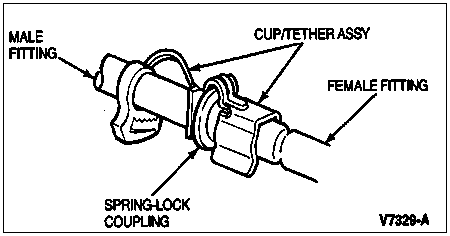
The spring lock coupling is a fuel tube coupling held together by a garter spring inside a circular cage. When the coupling is connected together, the flared end of the female fitting slips behind the garter spring inside the cage of the male fitting. The garter spring and cage then prevent the flared end of the female fitting from pulling out of the cage. As a redundant locking feature, a horseshoe shaped retaining clip is incorporated to improve the retaining reliability of the spring lock coupling.

Removal
Perform Pre-Service Procedures as described in Fuel Charging System in the Removal and Installation portion of this section.
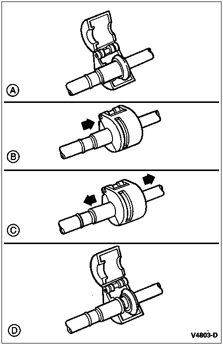
Remove retaining clip from spring lock coupling by hand only. Do not use any sharp tool or screwdriver as it may damage the spring lock coupling.
Twist fitting to free it from any adhesion at the O-ring seals.
Using Spring Lock Coupling Disconnect Tool T81P-18623-G1 (3/8 inch) or T81P-18623-G2 (1/2 inch), disconnect fuel hoses at the fuel rail supply tube and fuel rail return tube.

Installation
Make sure the garter spring is in cage of male fitting. If garter spring is missing, install a new spring by pushing it into cage opening. If garter spring is damaged, remove it from cage with a small wire hook (do not use a screwdriver) and install a new spring.
Clean all dirt or foreign material from both pieces of coupling.
![]() WARNING: USE ONLY THE SPECIFIED O-RINGS AS THEY ARE MADE OF A SPECIAL MATERIAL. THE USE OF ANY O-RING OTHER THAN THE SPECIFIED O-RING MAY ALLOW THE CONNECTION TO LEAK FUEL INTERMITTENTLY DURING VEHICLE OPERATION.
WARNING: USE ONLY THE SPECIFIED O-RINGS AS THEY ARE MADE OF A SPECIAL MATERIAL. THE USE OF ANY O-RING OTHER THAN THE SPECIFIED O-RING MAY ALLOW THE CONNECTION TO LEAK FUEL INTERMITTENTLY DURING VEHICLE OPERATION.
Replace missing or damaged O-rings.
Lubricate male fitting and O-rings and inside of female fitting with clean engine oil XO-10W30-QSP meeting Ford specification ESE-M2C153-E or equivalent.
Fit female fitting to male fitting and push until garter spring snaps over flared end of female fitting.
Make sure coupling is engaged by pulling on fitting and visually checking to make sure garter spring is over flared end of female fitting.
NOTE: All vehicles require the large black clip to be installed on the supply side fuel tube and the small gray clip to be installed on the return side fuel tube.
Position retaining clip over metal portion of spring lock coupling. Firmly push retaining clip onto spring lock coupling. Make sure horseshoe portion of clip is over the coupling. Do not install retaining clip over rubber fuel tube.
Perform Post-Service Procedures as described in Fuel Charging System in the Removal and Installation portion of this section.