Section 03-03: Engine Cooling | 1996 F-150, F-250, F-350, F-Super Duty, Bronco Vehicles and F-250, F-350 and F-Super Duty Vehicles with 7.3L Diesel Engines Workshop Manual |
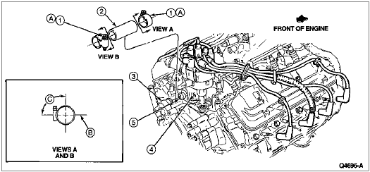
5.0L and 5.8L
Removal
Open hood (16612) and remove air cleaner outlet tubes (9B659).
Drain cooling system as outlined in Cooling System, Draining, Filling and Bleeding in the Cleaning and Inspection portion of this section.
Cut water bypass hose in half.
Compress hose clamps and slide toward center of bypass hose.
WARNING: IF WATER BYPASS TUBE (8548) HAS BEEN ON VEHICLE A LENGTH OF TIME, TWIST TO BREAK LOOSE BEFORE PULLING OFF. WATER BYPASS TUBE MAY SUDDENLY BREAK FREE, CAUSING HAND TO BE INJURED BY HITTING SHARP OBJECTS.
Twist water bypass tube to break loose seal and remove.
Installation
Position hose clamps on water bypass hose.
Put hose onto thermostat housing water pump nipples.
Slide hose clamps into place and release.
Refill cooling system as outlined in Cooling System, Draining, Filling and Bleeding in the Cleaning and Inspection portion of this section.
Install air cleaner outlet tubes.
Start engine (6007) and check for leaks. Retighten hose clamps (8287) after engine has warmed up.
Item | Part Number | Description |
---|---|---|
1 | 383522-S | Clamp |
2 | 8597 | Bypass Hose |
3 | 389772-S | Clamp |
4 | 8501 | Water Pump Assembly (Upper Nipple) |
5 | 8592 | Water Hose Connection |
A | — | Tighten to 1.6-2.2 Nm (15-20 Lb-In) |
B | — | Center Line Parallel to Intake Manifold Deck |
C | — | Align 10°-30° |
D | — | 1.5mm (0.06 Inch) Gap Typical |
E | — | 3.0mm (0.12 Inch) Maximum |
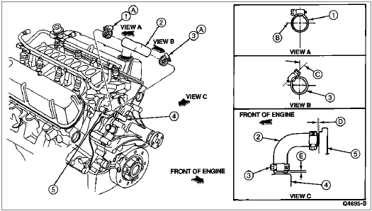
7.5L
Removal
Open hood and drain cooling system. Refer to Cooling System, Draining, Filling and Bleeding in the Cleaning and Inspection portion of this section.
Remove air cleaner outlet tubes.
Remove distributor (12127). Refer to Section 03-07A.
Compress hose clamps and slide toward middle of bypass hose.
Using sharp knife, cut old water bypass hose in two in the middle.
Remove the two halves of the water bypass hose. It may be necessary to pry against the intake manifold (9424) or water pump (8501) with a medium-bladed screwdriver to break loose water bypass hose from nipple.
Installation
Position hose clamps on bypass hose near the middle.
CAUTION: Do not kink hose. This breaks cords and may cause a permanent kink which could cause a coolant restriction.
Bend water bypass hose and work onto nipples. Do not bend water bypass hose so tightly that it kinks.
Position hose clamps and release.
Refill cooling system. Refer to Cooling System, Draining, Filling and Bleeding in the Cleaning and Inspection portion of this section.
Install and time distributor as outlined in Section 03-07A.
Start engine and check for leaks.
Install air cleaner outlet tubes.
Item | Part Number | Description |
---|---|---|
1 | 8287 | Hose Clamp |
2 | 8597 | Bypass Hose |
3 | 8501 | Water Pump |
4 | 9424 | Lower Intake Manifold |
5 | — | Nipple (Part of 9424) |
A | — | Tighten to 1.3-2.2 Nm (12-20 Lb-In) |
B | — | Center Line Parallel to Vertical Center Line of Engine |
C | — | 80°-100° |