![]() WARNING: DO NOT STAND IN LINE WITH OR NEAR RADIATOR FAN BLADE (8600) WHEN ENGINE IS RUNNING.
WARNING: DO NOT STAND IN LINE WITH OR NEAR RADIATOR FAN BLADE (8600) WHEN ENGINE IS RUNNING.
Check for leaks and proper coolant level after the engine has reached normal operating temperatures.

Section 03-03: Engine Cooling | 1996 F-150, F-250, F-350, F-Super Duty, Bronco Vehicles and F-250, F-350 and F-Super Duty Vehicles with 7.3L Diesel Engines Workshop Manual |
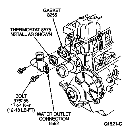
4.9L (300 CID) I-6
Do not attempt to service the water thermostat (8575). It should be replaced if it is not operating properly.
Check the water thermostat before installing it. Refer to Thermostat, Water Under Component Tests in the Diagnosis and Testing portion of this section.
Removal
Drain the radiator (8005) so that the coolant level is below the water thermostat. Refer to Cooling System Draining, Filling, and Bleeding in the Cleaning and Inspection portion of this section.
Remove the water hose connection (8592) attaching bolts.
Pull the hose connection away from the cylinder head (6049) sufficiently to provide access to the water thermostat.
Remove the water thermostat and gasket.
Installation
Clean the water hose connection and cylinder head gasket surfaces.
Coat a new gasket with Perfect Seal Sealing Compound B5A-19554-A or D7AZ-19554-BA or equivalent meeting Ford specifications ESR-M18P2-A and ESE-M4G115-A.
Position the gasket on the cylinder head opening. The gasket must be positioned on the cylinder head before the thermostat is installed.
The water hose connection contains a locking recess into which the water thermostat is turned and locked. Install the water thermostat with pellet side out.
Turn the water thermostat clockwise to lock it in position on the flats cast into the outlet elbow.
Position the water hose connection against the cylinder head. Install and tighten the attaching bolts to 16-24 Nm (12-18 lb-ft).
Fill and bleed the cooling system as described in Cooling System, Draining, Filling and Bleeding in the Cleaning and Inspection portion of this section.
![]() WARNING: DO NOT STAND IN LINE WITH OR NEAR RADIATOR FAN BLADE (8600) WHEN ENGINE IS RUNNING.
WARNING: DO NOT STAND IN LINE WITH OR NEAR RADIATOR FAN BLADE (8600) WHEN ENGINE IS RUNNING.
Check for leaks and proper coolant level after the engine has reached normal operating temperatures.

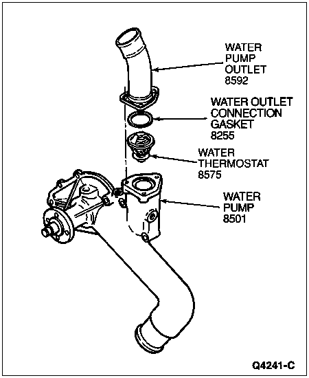
V-8, Gasoline
Removal
Drain the radiator so that the coolant level is below the water thermostat. Refer to Cooling System Draining, Filling and Bleeding in the Cleaning and Inspection portion of this section.
Disconnect the bypass hose at the water pump (8501) and water hose connection.
Remove the bypass tube.
Remove the water hose connection attaching bolts.
Bend the upper radiator hose (8260) upward and remove the water thermostat and water hose connection gasket (8255).
Installation
Clean the water outlet water hose connection gasket surfaces. Coat a new water hose connection gasket with Perfect Seal Sealing Compound B5A-19554-A or D7AZ-19554-BA or equivalent meeting Ford specifications ESR-M18P2-A or ESE-M4G115-A.
Position the water hose connection gasket on the intake manifold or cylinder head opening.
Install the water thermostat in the intake manifold opening with the copper pellet or element toward the engine (6007) and the thermostat flange positioned in the recess. If the water thermostat is improperly installed, it will cause a retarded flow of coolant.
Position the water hose connection against the intake manifold (9424) and install attaching bolts. If a 7.5L engine, tighten bolts to 32-37 Nm (23-38 lb-ft). For all other engines, tighten bolts to 16-24 Nm (12-18 lb-ft).
Install the water bypass line and tighten hose connections.
Fill and bleed the cooling system as described in Cooling System, Draining, Filling and Bleeding in the Cleaning and Inspection portion of this section.
![]() WARNING: DO NOT STAND IN LINE WITH OR NEAR RADIATOR FAN BLADE WHEN ENGINE IS RUNNING.
WARNING: DO NOT STAND IN LINE WITH OR NEAR RADIATOR FAN BLADE WHEN ENGINE IS RUNNING.
Operate the engine until normal operating temperature is reached; then check the coolant level and check for leaks.

| Item | Part Number | Description |
|---|---|---|
| 1 | 8255 | Water Outlet Connection Gasket |
| 2 | 8592 | Water Outlet Connection |
| 3 | 391428 | Screw, 5/16-18 x 1.25 |
| 4 | 8575 | Water Thermostat |
| 5 | 391430 | Screw 5/16-18 x 1.75 |
| A | — | Insert with Copper Pellet Towards Engine |
| B | — | Tighten in Sequence Indicated in Text to 16-24 Nm (12-18 Lb-Ft) |
Diesel
Removal
Drain the cooling system. Refer to Cooling System Draining, Filling and Bleeding in the Cleaning and Inspection portion of this section.
Disconnect the drive belt (8620) at the drive belt tensioner pulley (6B217).
Remove the upper radiator coolant hose clamp at the water hose connection and disconnect the upper radiator hose from the water hose connection.
Remove retaining screws and the water hose connection.
Remove the thermostat housing O-ring and water thermostat.

Installation
Install the water thermostat O-ring.
Position the water hose connection. Install retaining screws and tighten to 20 Nm (15 lb-ft).
Connect the upper radiator hose to the water hose connection and install hose clamp at the water hose connection.
Install the drive belt at the drive belt tensioner pulley.
Refill and bleed the engine cooling system as described in Cooling System, Draining, Filling and Bleeding in the Cleaning and Inspection portion of this section.