Section 03-01D: Engine, Diesel, 7.3L
1996 F-Series Workshop Manual
REMOVAL AND INSTALLATION

Piston and Connecting Rod


Removal

  1.  CAUTION: Do not use a power wrench for removing or installing connecting rod bolts (6214), or connecting rod nuts (6212). Power wrench usage will cause seizure of connecting rod bolt or connecting rod nut threads.

    Remove engine from vehicle and place on an engine stand. Remove cylinder heads (6049), oil pan (6675) and oil pan.
  1. Remove any ridges and/or deposits from upper end of cylinder bores as follows:

    1. Turn crankshaft (6303) until piston to be removed is at bottom dead center (BDC). Place a cloth on piston head to collect cuttings. Remove any ridge and/or deposits from upper end of cylinder bores.
    1. Remove cylinder ridge with a razor knife or equivalent. Carefully scrape ridge away.
  1. Mark all connecting rods (6200) and connecting rod caps to permit installation into original positions.

  1. Remove connecting rod nuts and connecting rod cap.

  1. Install rubber hose or equivalent onto connecting rod bolts.

  1. Push connecting rod and piston out top of cylinder with handle end of a hammer.Avoid damage to piston cooling oil jets (6C327), crankshaft journal or cylinder wall when removing piston and connecting rod.

  1. Remove connecting rod bearing (6211) from connecting rod and connecting rod cap.

  1. Install connecting rod cap onto connecting rod from which it was removed.

Installation

  1. Remove cylinder wall glaze if new piston rings are to be installed. Follow instructions of the tool manufacturer. Cylinder bores must be cleaned with a soap and water solution after deglazing or honing. Dry and oil cylinder walls immediately after cleaning. Use proper size ring installation tool.

  1.  CAUTION: Be sure to install pistons in same cylinders from which they were removed, or to which they were fitted. If a connecting rod is ever transposed from one cylinder block or cylinder to another, new connecting rod bearings should be fitted and connecting rod should be numbered to correspond with a new cylinder number.

    Oil piston rings, piston, and cylinder walls with specified engine oil.

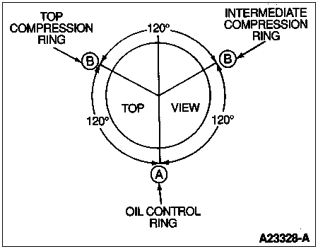
  1. Make sure ring gaps (oil control ring, compression rings) are properly spaced around circumference of piston. Refer to Piston Ring Spacing illustration.

    Piston Ring Spacing

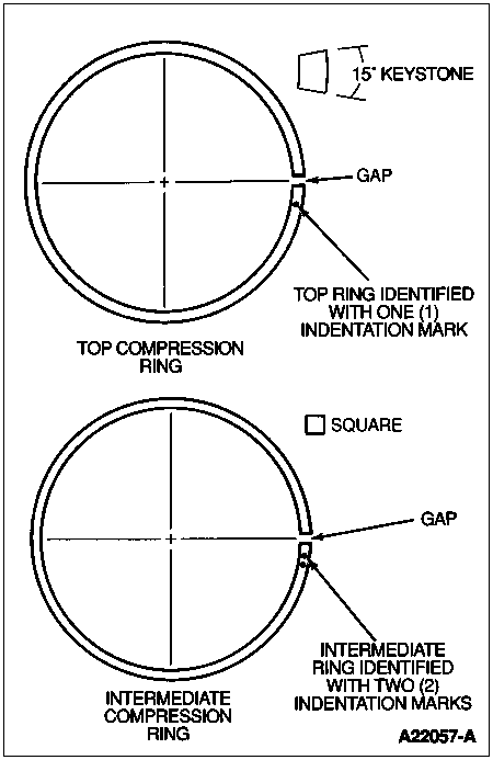
  1. Make sure the indentation marks on top two compression rings are facing up. Piston rings are identified by indents as shown in Ring Identification illustration.

    Ring Identification

  1. Turn crankshaft throw to position.

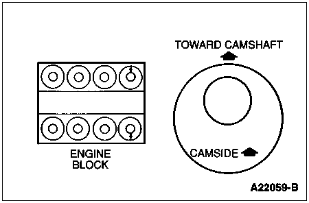
  1. Install upper connecting rod bearing. Install lengths of rubber hose onto connecting rod bolts. Before installing, make sure large chamfer on connecting rod faces crankshaft side, not opposite connecting rod (facing toward front of engine on right bank connecting rods, and toward rear of engine on left bank connecting rods). Install Piston Ring Compressor D81L-6002-C or equivalent onto piston and push piston in with a hammer handle until it is slightly below top of cylinder. Guide connecting rod to avoid damaging piston cooling oil jets and crankshaft journals.Install piston with arrow on piston head toward camshaft (6250).

    Piston Orientation

  1. Push piston downward until connecting rod bearing seats on crankshaft journal. Remove protective sleeves (rubber hose) and install lower connecting rod bearing and connecting rod cap.

  1. Check clearance of each connecting rod bearing and connecting rod side clearance following procedure described under Main Bearings and Connecting Rod Bearings in the Cleaning and Inspection portion of this section.

  1. Apply a light coat of specified engine oil to crankshaft journals and connecting rod bearings.

  1. NOTE: Lightly coat connecting rod bolt threads with oil before installing.

    Install connecting rod cap and lower connecting rod bearing. Initially tighten connecting rod nuts alternately to 71 Nm (52 lb-ft). Retighten connecting rod nuts alternately to 108 Nm (80 lb-ft).