Section 03-01D: Engine, Diesel, 7.3L | 1996 F-Series Workshop Manual |
Removal
Disconnect battery ground cables (14301).
Remove the generator retaining bolt and position the heater hose aside.
Remove the drive belt (8620).
Disconnect the generator electrical connectors.
Remove the generator bracket retaining bolts.
Remove the generator bracket (10A313) (with generator (GEN) (10300) attached).
Remove the oil level indicator bracket bolts, bracket and oil level dipstick (6750).
WARNING: RED-STRIPED WIRES CARRY 115V DC. SEVERE ELECTRICAL SHOCK MAY BE RECEIVED. DO NOT PIERCE.
CAUTION: Do not pierce engine electrical wires or damage to the harness may occur.
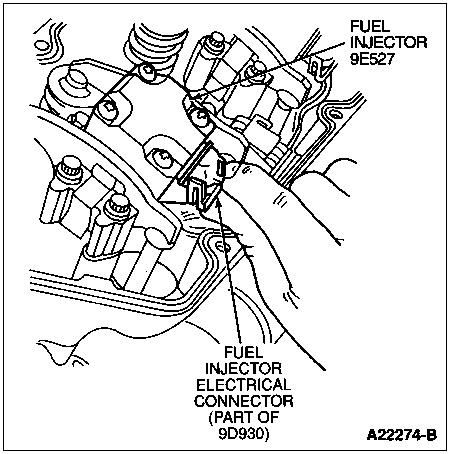
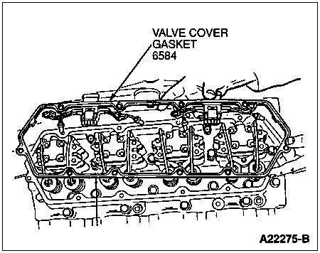
Remove the fuel injector harness clip and disconnect the engine harness electrical connectors from the valve cover gasket (6584).
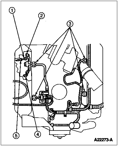
Item | Part Number | Description |
---|---|---|
1 | — | Fuel Injector Connector (Part of 9D930) |
2 | — | Glow Plug Connector (Part of 9D930) |
3 | — | Fuel Injector and Glow Plug Electrical Connectors to Rocker Arm Cover Gasket (Part of 12A581) |
4 | 12A342 | Glow Plug |
5 | 3802246 | Fuel Injector |
Remove the valve cover bolts and valve cover (6582).
Disconnect the electrical connectors from the fuel injector nozzle tip (9E527) and glow plugs.
Remove the valve cover gasket.
Remove the two rocker arm bolts (6A527).
Remove the rocker arm (6564) assembly.
Remove the push rod (6565).
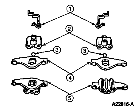
NOTE: Be careful when removing the rocker arm snap retaining clip. Do not lose the rocker arm steel ball.
Remove the snap retaining clip.
Remove the rocker arm and steel ball from the rocker arm pedestal.
Item | Part Number | Description |
---|---|---|
1 | — | Snap Retaining Clip (Part of 6564) |
2 | — | Rocker Arm Pedestal (Part of 6564) |
3 | — | Rocker Arm Ball (Part of 6564) |
4 | — | Rocker Arm (Part of 6564) |
5 | 6564 | Rocker Arm Assembly |
Installation
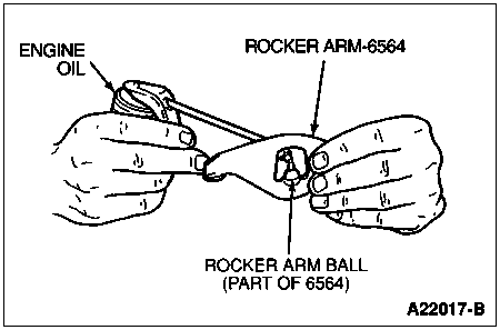
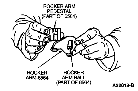
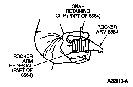
Assemble the intake rocker arm or exhaust rocker arm assembly as follows:
Item | Part Number | Description |
---|---|---|
1 | — | Snap Retaining Clip (Part of 6564) |
2 | — | Rocker Arm (Part of 6564) |
3 | — | Rocker Arm Pedestal (Part of 6564) |
4 | — | Rocker Arm Ball (Part of 6564) |
5 | 6564 | Rocker Arm Assembly |
Lubricate the push rod ends with engine oil and install the push rod (copper end up).
CAUTION: Failure to follow the next step of this procedure could result in bent valves, causing severe engine damage.
Rotate the engine until the mark on the crankshaft damper is at 11 o'clock to prevent valve damage when installing the intake rocker arm and exhaust rocker arm.
Install the push rods.
Install the intake rocker arm or exhaust rocker arm.
Install the two rocker arm bolts. Tighten rocker arm bolts evenly to 27 Nm (20 lb-ft).
Install the valve cover gasket.
Connect the electrical connectors to the fuel injectors and glow plugs.
Install the valve cover and retaining bolts. Tighten bolts to 11 Nm (97 lb-in).
Connect the engine harness electrical connectors to the valve cover gasket. Install the fuel injector harness clip.
Install the oil level indicator bracket, oil level dipstick and retaining bolts. Tighten bolts to standard torque specifications listed at the end of this section.
Install the generator bracket (with generator attached).
Install the generator bracket retaining bolts. Tighten bolts to 40-55 Nm (30-40 lb-ft).
Connect the generator electrical connectors.
Install the drive belt.
Reposition the heater hose and install the generator retaining bolt. Tighten bolt to 40-55 Nm (30-40 lb-ft).
NOTE: When the battery has been disconnected and reconnected, some abnormal drive symptoms may occur while the powertrain control module (PCM) relearns its adaptive strategy. The vehicle may need to be driven 16 km (10 miles) or more to relearn the strategy.
Reconnect battery ground cables.