Section 03-01D: Engine, Diesel, 7.3L | 1996 F-Series Workshop Manual |
Removal
Disconnect the battery ground cables and remove the engine cover.
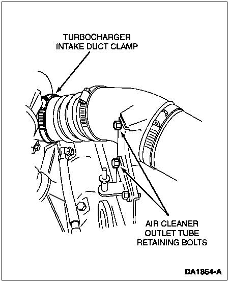
Remove the two (2) bolts retaining the air cleaner outlet tube to the support bracket on the left valve cover. Remove and discard the crankcase ventilation hose clamp and disconnect the hose. Loosen the clamp at the turbocharger. Remove the tube from the turbocharger and position out of the way.
Loosen the two (2) nuts at the exhaust outlet pipe-to-converter flange.
Remove the Marmon clamp at the turbocharger exhaust outlet.
NOTE: The intake manifold ports must be capped when the compressor manifold has been removed.
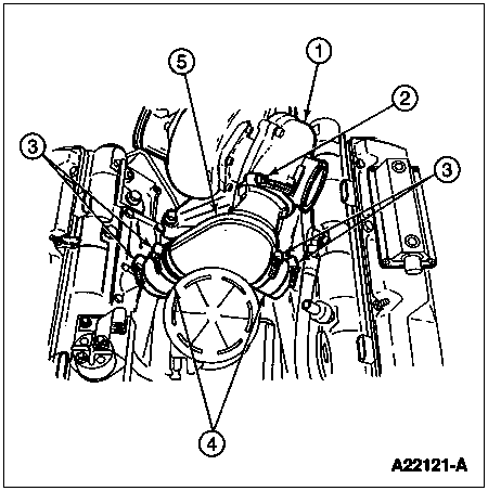
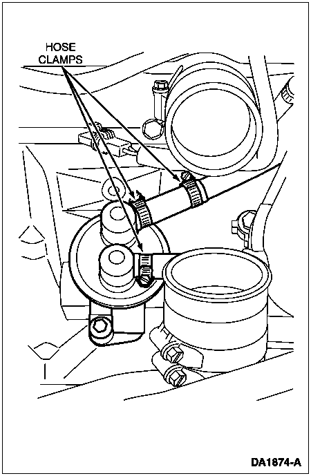
Loosen the two (2) upper hose clamps where the compressor manifold splits to the intake manifold and the Marmon clamp retaining the compressor manifold to the turbocharger. Remove the compressor manifold. Remove and discard the O-ring from the turbocharger.
Item | Part Number | Description |
---|---|---|
1 | — | Compressor Housing (Part of 6K889) |
2 | 8287 | Hose Clamp |
3 | 8287 | Manifold Hose Clamp |
4 | 1820075C1 | Intake Manifold Hose |
5 | 6K889 | Compressor Manifold |
Remove the two (2) bolts and the two (2) nuts retaining the exhaust inlet adapter to the turbocharger.
NOTE: Install Fuel/Oil/Turbo Protector Cap Set T94T-9395-AH if turbocharger is not being replaced.
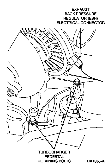
Install protective caps. Remove the four (4) bolts retaining the turbocharger pedestal assembly to the cylinder block. Disconnect the electrical connector from the turbocharger and remove the turbocharger pedestal assembly.
CAUTION: Take necessary precautions to prevent any debris from entering oil galleys and exhaust inlet adapter.
Remove and discard the oil galley O-rings and the exhaust inlet adapter gasket.
NOTE: The following procedure applies to both 49-state and California vehicles (49-state fuel pump shown, California fuel pump similar).
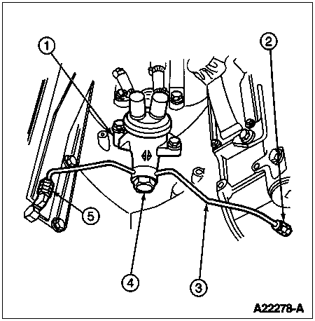
Remove the fuel line banjo bolt and washer from the fuel pump. Disconnect the fuel line fittings from the rear of the cylinder heads and remove the fuel line assembly.
Item | Part Number | Description |
---|---|---|
1 | 9350 | Fuel Pump |
2 | 9B254 | Fuel Line Fitting |
3 | 9A564 | Fuel Supply Line Assy |
4 | 9R549 | Banjo Bolt |
5 | 9B253 | Fuel Line Fitting |
Remove the fuel hose shield. Loosen the three (3) hose clamps at the fuel pump fittings.
Remove the fuel filter retaining bolts and position the fuel filter forward.
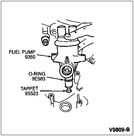
NOTE: If the tappet falls out of the fuel pump, the pump must be replaced.
Remove the fuel pump retaining bolts and lift the fuel pump out of the crankcase bore and disconnect the hoses. Remove the fuel pump tappet from the crankcase bore.
Clean the oil galley ports on the engine block and the turbocharger, and the exhaust inlet adapter and turbocharger gasket surface. Inspect the O-ring area of the compressor manifold and the turbocharger. Clean if necessary.
Installation
Rotate the engine so the fuel pump cam eccentric is on the base circle to ease installation and prevent possible damage of the fuel pump.
NOTE: If the tappet falls out of the fuel pump, the pump must be replaced.
Replace the O-ring on the fuel pump base.
Connect the hoses to the fuel pump. Position the fuel pump into the crankcase bore. Install the fuel pump bolts. Tighten the bolts to 32 Nm (24 lb-ft).
Position the fuel filter and install the retaining bolts. Tighten the bolts to 43 Nm (32 lb-ft).
Tighten the fuel hose and the water drain hose clamps securely. Install the fuel hose shield.
Replace the seal rings on the fuel line assembly. Loosely install the fuel line fittings at the rear of the cylinder heads. Install the banjo bolt and washer at the fuel pump. Tighten the bolt to 55 Nm (41 lb-ft).
Tighten the fuel line fittings at the rear of the cylinder heads securely.
Install new oil galley O-rings lubricated with engine oil and a new exhaust inlet adapter gasket.
Remove Fuel/Oil/Turbo Protector Cap Set (T94T-9395-AH). Position the turbocharger assembly and connect the electrical connector. Install the retaining bolts. Tighten to 24 Nm (18 lb-ft).
Install the two (2) bolts and the two (2) nuts at the exhaust inlet adapter. Tighten the retainers to 49 Nm (36 lb-ft).
Install the compressor manifold with a new O-ring at the turbocharger. Tighten the hose clamps and the Marmon clamp securely.
Position the exhaust outlet pipe to the turbocharger and install the Marmon clamp securely.
Tighten the two (2) nuts on the exhaust outlet pipe to converter flange to 49 Nm (36 lb-ft).
Position the air cleaner outlet tube and install the two (2) bolts to the support bracket. Tighten the bolts to 16 Nm (12 lb-ft). Tighten the clamps at the turbocharger inlet and the crankcase ventilation hose securely.
Install the engine cover and connect the battery ground cables.