Remove distributor to spark plug wires (12286) using Spark Plug Wire Remover T74P-6666-A.

Section 03-01C: Engine, 7.5L MFI | 1996 F-250, F-350, F-Super Duty Chassis Cab and Motorhome Workshop Manual |
| Description | Tool Number |
|---|---|
| Spark Plug Wire Remover | T74P-6666-A |
Right-Hand
Removal
Remove spark plug heat shield (12A406).
Remove distributor to spark plug wires (12286) using Spark Plug Wire Remover T74P-6666-A.

Disconnect muffler inlet pipe.
If equipped with secondary air injection, disconnect the secondary air injection check valve tube (9B480).
Remove attaching bolts and right exhaust manifold (9430).
Inspect joint faces for signs fo exhaust leaks, cracks or any defect that would make exhaust manifold unfit for use.
Left-Hand
Removal
Remove oil level indicator tube (6754).
Remove spark plug heat shield.
Remove distributor to spark plug wires using Spark Plug Wire Remover T74P-6666-A.
Disconnect EGR valve to exhaust manifold tube (9D477). If equipped with air injection, disconnect the secondary air injection check valve tube.
Disconnect muffler inlet pipe.
Remove attaching bolts and exhaust manifold (9431).
Inspect joint faces for signs of exhaust leaks, cracks or any defect that would make the exhaust manifold unfit for use.
Installation
Clean mating surfaces of right exhaust manifold or left exhaust manifold and cylinder head (6049). Clean mounting flange of right exhaust manifold or left exhaust manifold and inlet pipe(s). Clean mounting surface for air injection tube or right exhaust manifold. Apply light film of Premium Long-Life Grease XG-1-C or -K or equivalent meeting Ford specification ESA-M1C75-B to right exhaust manifold or left exhaust manifold.
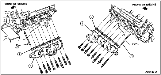
Position right exhaust manifold or left exhaust manifold on cylinder head. Install attaching bolts and washers, starting at fourth bolt hole from front of each right exhaust manifold or left exhaust manifold. Tighten bolts to 34-47 Nm (25-35 lb-ft), working from center right to both ends.

| Item | Part Number | Description |
|---|---|---|
| 1 | 9430 | Exhaust Manifold(RH) |
| 2 | 9448 | Exhaust Manifold Gasket (California Only) |
| 3 | — | Guide Pin (Part of 9428) |
| 4 | 9431 | Exhaust Manifold(LH) |
Position inlet pipes to right exhaust manifold or left exhaust manifold. Install attaching nuts and tighten to 34-47 Nm (25-35 lb-ft).
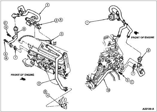
Position the secondary air injection check valve tube and the secondary air injection tube gasket (9C435) at rear of right-hand exhaust manifold. Install attaching bolts and tighten to 19-25 Nm (14-18 lb-ft).
Attach the secondary air injection manifold tube (9B449) to left-hand exhaust manifold fitting (located under EGR tube). Tighten nut to 30-40 Nm (22-30 lb-ft).
Attach the secondary air injection check valve tube to rear of right-hand cylinder head. Tighten bolts to 75-85 Nm (56-62 lb-ft).

| Item | Part Number | Description |
|---|---|---|
| 1 | 9G442 | Valve and Bracket Assembly |
| 2 | 45338-S36 | Nut |
| 3 | 19A05 | Ground Strap |
| 4 | 9A486 | Air Supply Pump Assembly |
| 5 | 9S433 | Hose Assembly |
| 6 | 56720-S2 | Bolt |
| 7 | 9C435 | Exhaust Air Supply Tube Gasket |
| 8 | 9B480 | Exhaust Air Supply Check Valve |
| 9 | 56558-S36 | Bolt |
| 10 | 9B449 | Exhaust Air Supply Manifold (LH) |
| A | — | Tighten to 19-25 Nm (14-18 Lb-Ft) |
| B | — | No Lubricants are to be Introduced to the Inside of the Pump Assembly |
| C | — | Tighten to 53-72 Nm (39-53 Lb-Ft) |
Connect EGR valve to exhaust manifold tube to left exhaust manifold, if removed. Tighten nut to 53-72 Nm (39-53 lb-ft).
Install spark plug heat shield and distributor to spark plug wires.
Install oil level indicator tube to left exhaust manifold, if removed. Tighten nut to 13-24 Nm (10-18 lb-ft).
Start engine (6007) and check for exhaust leaks.