Section 03-01C: Engine, 7.5L MFI | 1996 F-250, F-350, F-Super Duty Chassis Cab and Motorhome Workshop Manual |
Removal
Description | Tool Number |
---|---|
Spark Plug Wire Remover | T74P-6666-A |
EFI/CFI Fuel Pressure Gauge | T80L-9974-B |
Disconnect the negative battery cable. For additional information, refer to Section 14-01.
Drain the cooling system. For additional information, refer to Section 03-03.
Drain and evacuate the A/C system. For additional information, refer to Section 12-00.
Remove the air inlet tubes. Disconnect the air by-pass hose and remove the crankcase vent hose.
Loosen the fan-to-water pump bolts. Loosen the alternator adjusting bolts and remove the alternator belt. Rotate the drive belt tensioner counterclockwise and remove the A/C drive belt. For additional information, refer to Section 03-05.
Remove the fan and pulley from the water pump. Remove the fan shroud.
Remove the upper radiator hose. Remove the heater hoses from the radiator fill neck, water pump, and intake manifold. Loosen the clamps from the water pump by-pass hose.
Remove the alternator adjusting support bracket from the water pump. Disconnect the alternator harness and position aside. Remove the alternator. For additional information, refer to Section 14-02A.
Disconnect the diverter valve hose from the air management muffler. Disconnect the downstream hoses from the air management tubes. Remove the nuts retaining the air management tube brackets to the right exhaust manifold, and remove the brackets from the manifold. Remove the ground wire from tube brackets and position aside.
Disconnect the vacuum hoses from the EGR vacuum reservoir tank, air by-pass valve, and from the air management silencer on the right inner fender.
Remove the alternator bracket from the right cylinder head with the air pump, hoses and tubes attached.
Remove the engine-lifting eye from the front of the right cylinder head.
Disconnect the A/C compressor clutch, A/C high pressure cut-off, and the distributor connector and locator.
Remove the A/C manifold bolt from the rear of the compressor. Remove the A/C manifold lines and two locators. Install protective caps.
Remove the power steering pressure line and return hose. Install protective caps.
Remove the belt tensioner. Remove the A/C compressor and power steering pump bracket with the pump and compressor attached.
Disconnect the tube at the valve cover, and position the valve and tube out of the way. Disconnect the wiring connector from the canister purge solenoid.
Disconnect the spark plug wire boots, the locators, and the coil wire from the left and right side of the engine. Remove the distributor cap with wires attached.
Mark the relation of the rotor to the distributor housing and the distributor housing to the engine block for reassembly. Remove the distributor. For additional information, refer to Section 03-07A.
Remove the engine vacuum harness from the engine. Disconnect the air by-pass valve, TPS, EVP, EGR, IAC, locator, coil connector, radio noise suppressor, EVR, TAD solenoid, brake vacuum hose, and 42-pin electrical connector from left inner fender.
Remove the coil bracket assembly from the left exhaust manifold and intake. Remove the nut that retains the oil level indicator tube to the exhaust manifold and position the tube aside.
Disconnect the EGR tube flange nut from the EGR valve.
Remove the accelerator cable bracket and cable from the throttle body and position aside. Disconnect the MAP sensor vacuum hose.
Remove the upper intake manifold and tape the lower intake ports.
Remove the thermostat housing and discard the gasket. Disconnect the oil pressure-sending unit.
Depressurize the fuel system using EFI/CFI Fuel Pressure Gauge T80L-9974-B. For additional information, refer to Section 03-04B.
Remove the locking clips from the pressure and return fuel line spring lock couplings. Using spring lock coupling disconnect tools (D87L-9280-A, or equivalent, for 3/8-inch line, D87L-9280-B, or equivalent, for 1/2-inch line) disconnect the couplings. Install protective caps.
Remove the lower intake manifold with harness and injectors attached. Discard the gasket and tape the ports of cylinder heads.
Raise the vehicle. For additional information, refer to Section 00-02.
Remove the hose from the downstream air management tube to converter and remove the retaining bolt from the rear of the right cylinder head.
Remove the exhaust crossover pipe retaining nuts at the manifolds.
Remove the EGR valve tube from the left exhaust manifold. Remove the air management tube from the left exhaust manifold.
Lower the vehicle.
Remove the bolt from the rear of right cylinder head that retains the left air management tube. Remove the bolt retaining the fuel line bracket and transmission filler tube. Remove the filler tube and indicator.
NOTE: Identify the location of each rocker arm. Each rocker arm is to be installed in the original location to prevent premature wear. Identify the location of each push rod. Each push rod is to be installed in the original location to prevent premature wear.
Remove the left valve cover, rocker arms, and push rods.
NOTE: The two lower rear head bolts will stay in the head until the head is removed.
Remove the left cylinder head and gasket. Discard the gasket.
NOTE: Identify the location of each rocker arm. Each rocker arm is to be installed in the original location to prevent premature wear. Identify the location of each push rod. Each push rod is to be installed in the original location to prevent premature wear.
Remove the right valve cover, rocker arms, and push rods.
NOTE: The lower rear head bolt will stay in the head until the head is removed.
Remove the right cylinder head and gasket. Discard the gasket.
Remove the gaskets and clean both rocker covers.
Clean the upper intake manifold.
Clean the lower intake manifold.
Clean both cylinder heads and mating surfaces.
Installation
NOTE: If the cylinder head was removed for head gasket replacement, check cylinder head and cylinder block gasket surfaces for flatness. If left or right exhaust manifold was removed, coat cylinder head and exhaust manifold port areas with film of Premium Long-Life Grease XG-1-C or -K or equivalent meeting Ford specification ESA-M1C75-B and install left or right exhaust manifold to cylinder head.
Position the two long cylinder head attaching bolts in two rear lower bolt holes of the left and right cylinder heads. Place a long cylinder head attaching bolt in rear lower bolt hole of right cylinder head. Use rubber bands to retain bolts in position, above the head-to-block mating surface, until cylinder heads are installed.
Position new head gaskets on cylinder block, position over block dowels. Do not apply sealer to head gasket surfaces. Position the cylinder heads on the engine block and install remaining attaching bolts (longer bolts in lower row of bolt holes). Tighten all cylinder head attaching bolts in sequence shown in three steps: first to 95 Nm (70 lb-ft), then to 136 Nm (100 lb-ft), and finally to 176 Nm (130 lb-ft). When this procedure is used, it is not necessary to tighten bolts after extended operation.
Install push rods in original positions. Apply Engine Assembly Lube D9AZ-19579-D or equivalent meeting Ford specifications ESB-M1C93-B to valve stem tips and push rod ends. Make sure the lower ends of push rods remain seated in the valve tappets.
NOTE: Make sure the rocker arm seat base is inserted into its slot on the cylinder head before tightening the rocker arm seat bolts.
Lubricate and install the rocker arms in original positions. Tighten the rocker arm seat bolts to 30 Nm (22 lb-ft).
Install new valve cover gaskets. Install the valve covers and tighten the bolts to 12 Nm (9 lb-ft).
Position the secondary air injection tube between the head and the air management tube and install the mounting bolt. Install the fuel bracket and the transmission filler tube. Tighten the transmission filler tube bolt to 19 Nm (14 lb-ft).
Raise the vehicle.
Tighten the bolt to the rear of the right cylinder head that retains the left air management tube to 16 Nm (12 lb-ft).
Loosely install the EGR valve tube to the left exhaust manifold. Install the air management tube to the left exhaust manifold. Tighten tube to 40 Nm (30 lb-ft).
Install the hose to the downstream air management tube on the converter. Tighten the bolt on the rear of the right cylinder head to 20 Nm (15 lb-ft).
Tighten the fuel line bracket bolt to 52 Nm (38 lb-ft).
Install the exhaust crossover pipe retaining nuts. Tighten the nuts to 34 Nm (25 lb-ft).
Lower the vehicle.
NOTE: Apply a bead of Silicone Gasket and Sealant F6AZ-19562-AA or equivalent meeting Ford specification WSE-M4G323-A6 in four places where the cylinder head and cylinder block meet.
Remove the protective tape covering the ports of the cylinder heads. Install the intake manifold gaskets and seals.
NOTE: Connect the by-pass hose from the water pump to the intake manifold as you install the intake manifold.
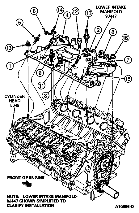
Install the lower intake manifold with harness and injectors attached. Tighten the retainers down in a three-step run-down procedure.Install the nuts onto studs in each corner of the intake. Tighten the bolts in sequence shown to 16 Nm (11 lb-ft). Then tighten the nuts to 16 Nm (11 lb-ft). Tighten the nuts and bolts down to 30 Nm (22 lb-ft) in sequence shown. Tighten nuts and bolts down to 47 Nm (35 lb-ft) in sequence shown. Repeat last step to make sure intake has seated.
NOTE: Lube, inspect, and replace the O-rings if necessary.
Remove the protective caps. Connect the pressure and return fuel line spring lock couplings. Install the locking clips. Connect the oil pressure-sending unit.
Install the thermostat housing and a new gasket. Tighten the bolts to 30 Nm (22 lb-ft). Tighten the intake-to-water by-pass hose clamp.
NOTE: Start the EGR exhaust tube to the EGR valve as the upper intake manifold is installed.
Remove the tape from the lower intake ports. Install the upper intake manifold and tighten to 14 Nm (10 lb-ft). Tighten EGR tube nut to 40 Nm (30 lb-ft).
Install the accelerator cable bracket and cable to the throttle body. Tighten the retainers to 17 Nm (13 lb-ft). Connect the canister purge valve tube to the valve cover and the MAP sensor vacuum line. Connect the wiring connector to the canister purge valve.
Install the distributor into engine using the alignment marks on the rotor, distributor housing, and engine block. Tighten the hold-down bolt to 17 Nm (13 lb-ft).
Install the coil bracket assembly to the left exhaust and intake manifolds. Tighten the nuts to 15 Nm (11 lb-ft). Install the nut that retains the oil level indicator tube to the exhaust manifold. Tighten the nut to 15 Nm (11 lb-ft).
Install the brake vacuum hose and engine vacuum harness. Connect the air by-pass valve, TPS, EVP, EGR, EVR, TAD solenoid, ignition coil, radio noise suppressor, and 42-pin electrical connectors to the left inner fender. Tighten the 42-pin electrical connector to 5 Nm (45 lb-in).
Install the distributor cap. Connect spark plug boots, locators, and coil wire.
Position the A/C and P/S mounting bracket over the water pump stud and secure to cylinder head with four bolts tightened to 54 Nm (40 lb-ft). Tighten bracket-to-water pump nut to 41 Nm (30 lb-ft).
Remove protective caps and install the power steering return line. Remove caps and replace power steering pressure line Teflon seal using tool D90P-3517-A. Install the pressure line. Tighten the line fitting to 35 Nm (25 lb-ft).
NOTE: Lube the O-rings with A/C refrigerant oil. Inspect and install new O-rings as necessary.
Install the two locators at the bulkhead. Remove the protective caps. Inspect and lube the O-rings with A/C refrigerant oil. Install the A/C manifold lines to the A/C compressor. Tighten the bolt to 18 Nm (13 lb-ft). Position the vacuum hose for the heater control.
Connect the discharge line at the condenser. Tighten the fitting to 24 Nm (17 lb-ft).
Connect the line at the suction accumulator drier. Tighten the fitting to 44 Nm (32 lb-ft).
Connect the A/C coil connector, A/C high pressure cut-off, and the distributor connector and locator.
Install the engine-lifting eye to the front of the right head. Tighten the bolts to 34 Nm (25 lb-ft). Install the belt tensioner and tighten the bolt to 68 Nm (50 lb-ft).
Install the alternator mounting bracket to the right cylinder head. Tighten bolts to 54 Nm (40 lb-ft).
Install the alternator adjusting arm bracket to the water pump. Tighten the bolts to 41 Nm (30 lb-ft). Loosely install the alternator. Connect the alternator harness and tighten the nut to 9 Nm (80 lb-in).
Connect the vacuum hose to the diverter and valve hose to the air management muffler. Connect the hose to the air pump silencer. Install the nuts to the right exhaust manifold retaining the air management tube brackets. Tighten the nuts to 17 Nm (13 lb-ft). Install the ground wire on the tube bracket. Tighten the nut to 10 Nm (89 lb-in).
Connect the downstream hose from tube, and hose from the emission tubes from the rear of each cylinder head. Connect the vacuum connectors to the EGR vacuum reservoir tank.
Raise the vehicle.
Position a drain pan and drain the engine oil.
Remove the drain pan.
Tighten the EGR valve tube to exhaust manifold to 40 Nm (30 lb-ft).
Lower the vehicle.
Install the heater hoses to the water pump and to the intake manifold.
Install the fan shroud. Install the water pump pulley and fan to water pump hub with four bolts. Tighten the water pump pulley and fan bolts to 16 Nm (12 lb-ft). Tighten the shroud bolts to 6 Nm (53 lb-in).
Install all drive belts and adjust. Tighten the alternator bolts to 24 Nm (18 lb-ft). For additional information, refer to Section 03-05.
Install the upper radiator hose. Install the heater hose to the radiator fill neck. Install the bolts retaining the tube to the radiator. Tighten the bolts to 5 Nm (44 lb-in).
Install the air inlet tubes and connect the air by-pass hose. Install the crankcase breather hose.
Fill the cooling system.
Fill the crankcase with the correct viscosity and amount of engine oil.
Evacuate and recharge the A/C system. For additional information, refer to Section 12-03A.
Connect the negative battery cable. For additional information, refer to Section 14-01.
Start the engine and check for oil leaks.
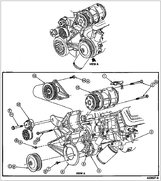
Item | Part Number | Description |
---|---|---|
1 | 19B890 | Air Conditioning Hose Assy |
2 | N806020-S2 | Bolt, M8-1.25 x 123 |
3 | 6754 | Oil Level Indicator Tube |
4 | 3A674 | Power Steering Pump |
5 | 388112 | Stud |
6 | 2882 | A/C Compressor Mounting Bracket |
7 | N800199-S8M | Screw, M10-1.5 x 33 |
8 | 3A733 | Power Steering Pump Pulley |
9 | 382802-S2 | Nut, 3/8-16 |
10 | 391319-S2 | Bolt, 7/16-14 x 5.25 |
11 | 56192-S2 | Bolt, 1/2-13 x 3.75 |
12 | 6B209 | Drive Belt Tensioner |
13 | 8678 | Belt Idler Pulley |
14 | N605790-S2 | Bolt, M8-1.25 x 40 |
15 | 19703 | A/C Compressor |
A | — | Tighten to 24-31 Nm (18-23 Lb-Ft) |
B | — | Tighten to 41-54 Nm (30-40 Lb-Ft) |
C | — | Press Flush ± 0.254 mm (0.010 Inch) |
D | — | Tighten to 54-71 Nm (40-53 Lb-Ft) |
E | — | Tighten to 68-92 Nm (50-68 Lb-Ft) |
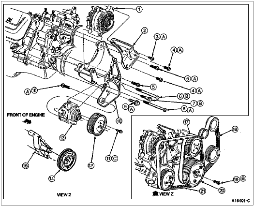
Item | Part Number | Description |
---|---|---|
1 | 10300 | Generator |
2 | 10145 | Generator Adjusting Arm |
3 | 390785-S36 | Screw, 3/8-16 x 1.25 — Used with Small Frame Generator |
4 | 56540-S36 | Bolt, 3/8-16 x 1.0 |
5 | 56542-S2 | Bolt, 3/8-16 x 1.5 |
6 | 391319-S2 | Bolt, 7/16-14 x 5.50 |
7 | 56564-S2 | Bolt, 7/16-14 x 2.0 |
8 | 391314-S2 | Bolt, 3/8-16 x 5.25 |
9 | 56544-S36 | Bolt, 3/8-16 x 2.0 |
10 | 10153 | Generator Mounting Bracket |
11 | N802493-S2 | Screw and Washer, M6-1.0 x 16 |
12 | 9B447 | Secondary Air Injection Pump Pulley |
13 | 9A486 | Secondary Air Injection Pump |
14 | 19A216 | Idler Assy (California, Only) |
15 | 8A620 | Idler Support Bracket (California Only) |
16 | 56543-S36 | Bolt, 3/8-16 x 1.75 |
17 | 8509 | Water Pump Pulley |
18 | 8620 | Drive Belt, 6k x 67.5 w/o A/C and 6k x 68.6 with A/C |
19 | 42998-S36 | Bolt, 3/8-16 x 1.0 |
20 | 6312 | Crankshaft Pulley |
21 | 8620 | Drive Belt, 6k x 49.5 — Small and Medium Frame Generator 6k x 50.5 — Large Frame Alternator |
A | — | Tighten to 41-54 Nm (30-40 Lb-Ft) |
B | — | Tighten to 54-71 Nm (40-53 Lb-Ft) |
C | — | Tighten to 12-15 Nm (9-11 Lb-Ft) |