Section 03-01B: Engine, 5.0L and 5.8L MFI | 1996 F-150, F-250, F-350 and Bronco Vehicles Equipped with 5.0L or 5.8L MFI Engines Workshop Manual |
| Description | Tool Number |
|---|---|
| Engine Lifting Bracket Tool | T70P-6000 |
| Multiport Fuel Injection (MFI) Fuel Pressure Gauge | T80L-9974-B |
| Spring Lock Coupling Disconnect Tool (3/8") | D87L-9280-A |
| Spring Lock Coupling Disconnect Tool (1/2") | D87L-9280-B |
| Spreader Bar | 303-F047 |
Removal
Disconnect negative battery cable. Refer to Section 14-01.
Drain cooling system. Refer to Section 03-03.
Discharge and recover refrigerant from A/C system. Refer to Section 12-00.
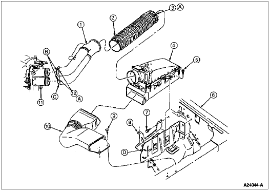
Remove jack handle. Remove pushpin retainers from air intake duct and remove duct from air cleaner assembly.

| Item | Part Number | Description |
|---|---|---|
| 1 | 9B659 | Air Cleaner Outlet Tube |
| 2 | 9B647 | Lower Air Cleaner Outlet Tube |
| 3 | | Hose Clamp (Part of 9B647) |
| 4 | 9600 | Engine Air Cleaner |
| 5 | N611062-S2 | Screw and Washer Assembly (3 Req'd) |
| 6 | 16005 | Left Fender |
| 7 | N610958-S2 | Screw (3 Req'd) |
| 8 | 9626 | Engine Air Cleaner Mounting Bracket |
| 9 | 388577-S150 | Pushpin (2 Req'd) |
| 10 | 9A624 | Engine Air Cleaner Intake Tube |
| 11 | 9E926 | Throttle Body |
| 12 | | Hose Clamp (part of 9R504) |
| A | | Tighten to 1.5-2.5 Nm (14-22 Lb-In) |
| B | | Use Water or Rubber Lubricant D9AZ-19583-A or equivalent to facilitate installation of hose assembly to throttle body |
| C | | Surface must meet against throttle body stop flange for 360 degrees (both tubes) |
| D | | Water bottle affixed at this location |
Remove radiator overflow hose from radiator and position it out of way. Remove upper radiator air deflector. Remove retainer screws from fan shroud. Lift and position fan shroud over fan.
Remove throttle body shield retaining bolts and shield. Disconnect upper spacer plate heater hose at throttle body.
Disconnect radiator hoses from radiator.
Disconnect automatic transmission oil cooling lines from radiator fittings.
Remove upper radiator retaining bolts. Tilt radiator back and lift it directly upward, clear of radiator support bracket and fan blade.
Remove fan shroud. Remove retaining bolts from fan blade/clutch assembly and remove assembly.

Release tension from serpentine drive belt and remove belt. Remove water pump pulley.
Remove hoses from the engine.
Loosen air cleaner outlet tube hose clamps at throttle body and air cleaner assembly. Loosen hose clamp on breather hose at valve cover and remove hose. Remove air cleaner outlet tube.

| Item | Part Number | Description |
|---|---|---|
| 1 | 9B659 | Air Cleaner Outlet Tube |
| 2 | 9B647 | Lower Air Cleaner Outlet Tube |
| 3 | | Hose Clamp (Part of 9B647) |
| 4 | 9600 | Engine Air Cleaner |
| 5 | N611062-S2 | Screw and Washer Assembly (3 Req'd) |
| 6 | 16005 | Left Fender |
| 7 | N610958-S2 | Screw (3 Req'd) |
| 8 | 9626 | Engine Air Cleaner Mounting Bracket |
| 9 | 388577-S150 | Pushpin (2 Req'd) |
| 10 | 9A624 | Engine Air Cleaner Intake Tube |
| 11 | 9E926 | Throttle Body |
| 12 | | Hose Clamp (part of 9R504) |
| A | | Tighten to 1.5-2.5 Nm (14-22 Lb-In) |
| B | | Use Water or Rubber Lubricant D9AZ-19583-A or equivalent to facilitate installation of hose assembly to throttle body |
| C | | Surface must meet against throttle body stop flange for 360 degrees (both tubes) |
| D | | Water bottle affixed at this location |
Disconnect electrical connectors from A/C compressor and position out of way. Loosen retaining bolt for A/C manifold lines from compressor. Remove lines.
Remove A/C compressor retaining bolts and remove compressor.
Remove A/C and power steering support retaining bolts. Position and secure support and power steering pump assembly out of way.
![]() CAUTION: When disconnecting throttle cable from ball stud, use a screwdriver (or similar tool) close to stud and pry slowly. Pulling by hand could damage cable.
CAUTION: When disconnecting throttle cable from ball stud, use a screwdriver (or similar tool) close to stud and pry slowly. Pulling by hand could damage cable.
Disconnect throttle linkage at throttle ball. Remove bolts retaining accelerator cable bracket to intake manifold. Position accelerator cable bracket with cables out of way.
Disconnect electrical connectors at Idle Air Control (IAC) valve, throttle position sensor (TPS), EGR transducer, and two wiring locator pins.
Disconnect EGR transducer hoses from transducer. Remove bolts retaining transducer bracket and remove transducer.
Disconnect canister purge line from fitting on throttle body. Disconnect vacuum line from EGR valve. Disconnect EGR tube from EGR valve.
Disconnect vacuum lines from upper intake manifold vacuum tree and vacuum line from fuel pressure regulator. Disconnect PCV hose from fitting on top front of upper intake manifold.
Remove bolt retaining heater hose tube to generator. Compress clamp on heater hose at water pump, remove hose, and position it out of way. Compress clamp on heater hose at intake manifold, remove hose, and position it out of way.
Remove remaining generator retaining bolts. Remove generator and position it out of way.
Remove both hoses from air pump.
Remove three generator and air pump bracket retaining bolts. Remove bracket and air pump assembly.
Remove nut retaining starter motor harness and transmission cooler line brackets to front of engine block. Remove harness and cooler line brackets. Remove stud retaining ground cable.
Remove nut retaining ground wire and transmission filler tube bracket to upper intake support bracket. Position ground wire out of way. Remove upper filler tube and indicator from lower filler tube. Remove studded bolt retaining support bracket to upper intake manifold.
Disconnect lower heater line from throttle body.
Disconnect electrical block from left fender by loosening retaining bolt and separating it. Position harness over engine.
Remove five bolts and one Torx® bolt retaining upper intake manifold. Remove upper intake manifold and throttle body as an assembly. Discard gasket.
![]() WARNING: FUEL SUPPLY LINES ON VEHICLES EQUIPPED WITH FUEL INJECTED ENGINES REMAIN PRESSURIZED FOR LONG PERIODS OF TIME, AFTER ENGINE SHUT DOWN. FUEL SYSTEM PRESSURE MUST BE RELIEVED PRIOR TO FUEL SYSTEM SERVICE, TO PREVENT POSSIBLE INJURY.
WARNING: FUEL SUPPLY LINES ON VEHICLES EQUIPPED WITH FUEL INJECTED ENGINES REMAIN PRESSURIZED FOR LONG PERIODS OF TIME, AFTER ENGINE SHUT DOWN. FUEL SYSTEM PRESSURE MUST BE RELIEVED PRIOR TO FUEL SYSTEM SERVICE, TO PREVENT POSSIBLE INJURY.
Remove protective cap from fuel pressure relief valve. Connect Multiport Fuel Injection (MFI) Fuel Pressure Gauge (EFI/CFI) T80L-9974-B to fuel pressure relief valve on fuel injection supply manifold. Place end of adapter in a suitable container. Open manual valve of tool to relieve fuel system pressure. Close manual valve and disconnect tool from relief valve. Remove container and install protective cap.
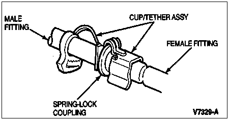
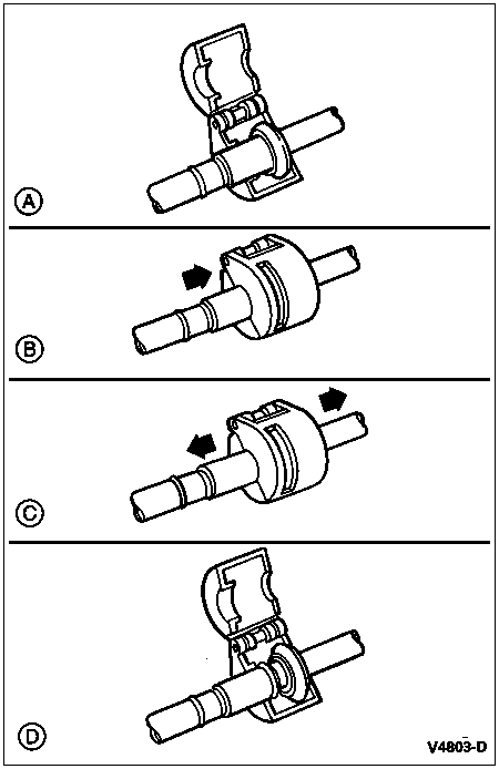
Remove locking clips from pressure and return fuel line spring lock couplings.

NOTE: Inspect couplings for missing or damaged O-rings. If either O-ring is damaged, both O-rings must be replaced. Replace O-rings or garter springs only with appropriate replacement parts.
Position a Spring Lock Coupling Disconnect Tool (D87L-9280-A for 3/8-inch line, D87L-9280-B for 1/2-inch line) on couplings. Push tool into cage opening to release female fitting from garter spring. Remove tool and pull male coupling and fitting apart.

Remove PCV valve and hose from right valve cover. Disconnect vacuum lines from EVR and vacuum solenoids at left valve cover. Disconnect vacuum lines from air diverter/bypass valve. Disconnect vacuum harness holders from right valve cover. Remove vacuum harness and position it out of way.
Loosen clamp and remove lower hose from air diverter/bypass valve. Loosen clamp and remove air diverter/bypass valve hose from thermactor air check valve.
Remove nuts retaining air inlet tube to right exhaust manifold. Remove air diverter/bypass valve and tube assembly.
NOTE: The bolts of this step also retain fuel line routing bracket.
Remove two upper converter housing-to-engine retaining bolts. Position lines and bracket out of way.
NOTE: If engine is not going to be reinstalled, replacement engine must now be mounted to an engine stand.
Install engine lifting brackets to rear of right exhaust manifold and to front of left exhaust manifold.
Raise vehicle.
Drain engine oil.
Remove starter motor heat shield. Remove starter retaining bolts and secure starter.
Remove exhaust manifold-to-exhaust pipe nuts.
Remove torque converter dust cover retaining bolts and remove cover. Remove bolt retaining rear engine plate to transmission.
NOTE: Use crankshaft pulley bolt to rotate converter. Mark converter stud and flexplate to aid during assembly.
Remove converter-to-flexplate nuts.
Remove remaining converter housing-to-engine retaining bolts.
Remove engine mount retaining nuts.
Lower vehicle.
NOTE: Position a block of wood on a floor jack to protect transmission.
Position floor jack under front of transmission and slightly raise it.
Position and connect Rotunda Floor Crane 077-00043 and Spreader Bar 303-F047 to lifting brackets. Slightly raise engine and carefully separate engine from transmission. Carefully lift engine out of engine compartment.
Installation
Position paint marks at 12 o'clock position on both torque converter stud and flexplate.
NOTE: Make sure studs on torque converter align with holes in flexplate.
Carefully lower engine into engine compartment. Align torque converter studs with holes in flexplate. Fully engage engine to transmission. Lower engine into position. Lower floor jack and remove it from under vehicle. Disconnect and remove floor crane from lifting brackets.
Position fuel line bracket and install two upper converter housing-to-engine retaining bolts. Tighten bolts to 61 Nm (45 lb-ft).
Raise vehicle.
Install remaining converter housing-to-engine retaining bolts. Tighten bolts to 61 Nm (45 lb-ft).
Install both of engine mount retaining nuts. Tighten nuts to 86 Nm (63 lb-ft).
NOTE: Use crankshaft pulley bolt to rotate converter.
Install new torque converter-to-flexplate nuts. Tighten nuts to 40 Nm (30 lb-ft).
Install torque converter dust cover and retaining bolts. Tighten bolts to 21 Nm (15 lb-ft). Install engine spacer plate-to-transmission retaining bolt. Tighten bolt to 20 Nm (15 lb-ft).
Position exhaust system and install manifold-to-exhaust pipe retaining nuts. Tighten nuts to 40 Nm (30 lb-ft).
Install starter motor and retaining bolts. Tighten bolts to 24 Nm (18 lb-ft). Install starter motor shield.
Lower vehicle.
Remove engine lifting brackets from exhaust manifolds.
Install ground cable and retaining stud to right front of engine block. Tighten stud to 23 Nm (17 lb-ft).
Install transmission cooler line bracket onto stud. Install retaining nut and tighten it to 20 Nm (15 lb-ft).
Install air inlet tube and air diverter/bypass valve assembly onto right exhaust manifold studs and install retaining nuts. Tighten nuts to 28 Nm (21 lb-ft).
Install lower hose to air diverter/bypass valve and securely tighten clamp. Install hose from air diverter/bypass valve to thermactor air check valve and tighten clamp. Position vacuum harness over right valve cover and engine. Connect vacuum harness holders to valve cover. Connect vacuum lines to fuel pressure regulator valve, Secondary Air Injection Control Solenoid Vacuum valve, solenoid valves, and air diverter/bypass valve. Install PCV valve and hose.
NOTE: If necessary, replace O-rings.
Lubricate O-rings. Remove protective caps. Connect fuel pressure and return line couplings. Pull on fittings to verify proper coupling engagement and install safety clips.
Clean upper intake manifold.
Position a new gasket on lower intake manifold. Install upper intake manifold and throttle body assembly to lower intake manifold, making sure gasket remains in place. Install five bolts and one Torx® bolt. Tighten bolts to 20 Nm (15 lb-ft).
Connect vacuum lines to upper intake manifold vacuum tree and vacuum line to fuel pressure regulator. Connect PCV hose to fitting on top front of upper intake manifold.
NOTE: Inspect O-ring on filler tube, replace it if necessary.
Position support bracket to upper intake manifold and install retaining stud. Tighten stud to 23 Nm (17 lb-ft). Lube O-ring and install upper filler tube into lower filler tube. Position filler tube bracket and ground wire over stud. Install retaining nut and tighten it to 14 Nm (10 lb-ft).
Position generator and air pump bracket with air pump to right cylinder head and install three retaining bolts. Tighten bolts to 47 Nm (35 lb-ft).
Connect both hoses to air pump and securely tighten hose clamps.
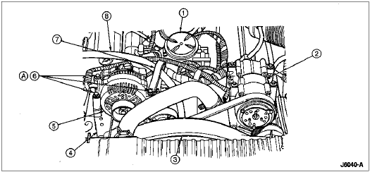
Position generator onto bracket and loosely install two lower bolts. Install heater hoses to water pump and intake manifold. Compress and install hose clamps. Position heater hose and bracket to upper generator mounting hole. Install upper generator bolt. Tighten bolts to 47 Nm (35 lb-ft).

| Item | Part Number | Description |
|---|---|---|
| 1 | | Fuel Filter Assembly (Part of 9K601) |
| 2 | 19703 | A/C Compressor |
| 3 | 8146 | Fan Shroud |
| 4 | 10A313 | Generator Bracket |
| 5 | 10346 | Generator |
| 6 | 389706-S2 | Generator Retaining Bolts (3 Req'd) |
| 7 | | Heater Hose Clip |
| 8 | | Heater Hose |
| A | | Tighten to 21-29 Nm (16-21 Lb-Ft) |
Install A/C and power steering pump support bracket with power steering pump assembly to right cylinder head. Install and tighten retaining bolts to 62 Nm (46 lb-ft).
Connect EGR tube to external pressure valve by installing flange nut. Tighten nut to 22 Nm (16 lb-ft). Connect vacuum line to EGR valve and canister purge solenoid. Install transmission fluid level indicator.
Install EGR transducer and bracket to upper intake manifold. Tighten bolts to 14 Nm (10 lb-ft). Connect EGR transducer hoses to EGR tube. Connect following electrical connections: IAC valve, TPS, and EGR transducer. Connect two wiring locators.
Install lower heater hose to throttle body and securely tighten clamp.
Compress hose clamp and install lower radiator hose to engine.
Install A/C compressor and retaining bolts. Tighten bolts to 27 Nm (20 lb-ft).
Install A/C manifold lines to compressor. Tighten retaining bolt to 18 Nm (13 lb-ft). Connect electrical connectors to A/C compressor.
NOTE: The electrical harness must run between A/C manifold lines.
Connect electrical block at left fender and securely tighten bolt.
Install accelerator cable bracket and cables to upper intake manifold. Tighten bolts to 12 Nm (9 lb-ft). Connect throttle cable to throttle ball.
Position water pump pulley on water pump. Install fan blade and fan clutch assembly onto water pump and install retaining bolts. Tighten bolts to 20 Nm (15 lb-ft).

Install serpentine drive belt, as detailed on underhood sticker for belt installation.
Position fan shroud over fan blade. Carefully lower radiator into vehicle, guiding locator pins into grommets. Install and tighten retaining bolts to 12 Nm (9 lb-ft).
Compress hose clamp on lower radiator hose, install hose onto radiator, and position clamp.
Connect automatic transmission oil cooling lines to radiator connectors. Tighten tube nuts to 20 Nm (15 lb-ft).
Position fan shroud into lower retainer clips and install upper retaining bolts. Tighten bolts to 8 Nm (71 lb-in).
Install upper heater hose to throttle body and securely tighten hose clamp. Attach radiator overflow hose to radiator.
Compress clamps on upper radiator hose, install hose, and position clamps.
Install upper radiator air deflector. Install air intake duct into air cleaner assembly and install pushpin retainers. Install air cleaner outlet tube to throttle body and air cleaner assembly.

| Item | Part Number | Description |
|---|---|---|
| 1 | 9B659 | Air Cleaner Outlet Tube |
| 2 | 9B647 | Lower Air Cleaner Outlet Tube |
| 3 | | Hose Clamp (Part of 9B647) |
| 4 | 9600 | Engine Air Cleaner |
| 5 | N611062-S2 | Screw and Washer Assembly (3 Req'd) |
| 6 | 16005 | Left Fender |
| 7 | N610958-S2 | Screw (3 Req'd) |
| 8 | 9626 | Engine Air Cleaner Mounting Bracket |
| 9 | 388577-S150 | Pushpin (2 Req'd) |
| 10 | 9A624 | Engine Air Cleaner Intake Tube |
| 11 | 9E926 | Throttle Body |
| 12 | | Hose Clamp (part of 9R504) |
| A | | Tighten to 1.5-2.5 Nm (14-22 Lb-In) |
| B | | Use Water or Rubber Lubricant D9AZ-19583-A or equivalent to facilitate installation of hose assembly to throttle body |
| C | | Surface must meet against throttle body stop flange for 360 degrees (both tubes) |
| D | | Water bottle affixed at this location |
Install breather hose to left valve cover. Securely tighten hose clamps.
Install throttle body shield. Securely tighten retaining bolts. Install jack handle.
Install negative battery cable.
Fill cooling system. Refer to Section 03-03.
Fill engine with oil.
Evacuate, pressurize, leak test, and recharge A/C system. Refer to Section 12-00.
Check operation of engine.