Section 03-01A: Engine, 4.9L SFI
1996 F-150, F-250, F-350 (4x2), F-150, F-250 (4x4) Workshop Manual
DISASSEMBLY AND ASSEMBLY

Valve Tappet, Hydraulic

NOTE: Each valve tappet (6500) is a matched assembly. If the parts of one valve tappet are mixed with those of another, improper valve operation may result. Disassemble and assemble each valve tappet separately. Keep the valve tappet assemblies in proper sequence so that they can be installed in their original bores.

Disassembly

  1. Grasp the lock ring with needlenose pliers to release it from the groove. It may be necessary to depress the plunger to fully release the lock ring.

  1. Remove the push rod cup, metering valve (disc), plunger and spring.

  1. Invert the plunger assembly and remove the check valve retainer by carefully prying up on it with a screwdriver. Remove the check valve (disc or ball check) and spring.

  1. For cleaning and inspection procedures, refer to Section 03-00.
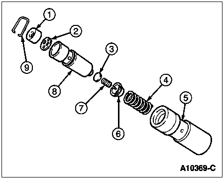
    ItemPart NumberDescription
    1Push Rod Cap (Part of 6500)
    2Metering Valve Disc
    (Part of 6500)
    3Check Valve (Part of 6500)
    4Plunger Spring (Part of 6500)
    5Body (Part of 6500)
    6Check Valve Retainer
    (Part of 6500)
    7Check Valve Spring
    (Part of 6500)
    8Plunger (Part of 6500)
    9Lock Ring (Part of 6500)

Assembly

NOTE: Valve tappets should always be tested after assembly. Refer to the test procedures in Section 03-00.

  1. Place the plunger upside down on a clean work bench.

  1. Place the check valve (disc or ball check) in position over the oil hole on the bottom of the plunger. Set the check valve spring on top of the check valve (disc or ball check).

  1. Position the check valve retainer over the check valve and spring. Push the retainer down into place on the plunger.

  1. Place the plunger spring and then the plunger (open end up) into the tappet body.

  1. Position the metering valve (disc) in the plunger and then place the push rod cup in the plunger.

  1. Depress the plunger and position the closed end of the lock ring in the groove of the tappet body. WIth the plunger still depressed, position the open ends of the lock ring in the groove. Release the plunger and then depress it again to fully seat the lock ring.

  1. Use the hydraulic valve tappet leak-down tester to fill the valve tappets with test fluid. Refer to Section 03-00.


Cylinder Block Assembly

Disassembly

  1. Mount the engine (6007) in a work stand.

  1. Remove the cylinder head (6049) and intake and exhaust manifolds.

  1. Remove all serviceable parts not furnished with the new cylinder block assembly, including the cylinder block drain plugs and cylinder head to block dowels (6A008).

Assembly

  1. Clean the gasket and seal surfaces of all serviceable parts and assemblies.

  1. Position the new cylinder block (6010) assembly in a work stand and transfer all serviceable parts removed from the old cylinder block assembly.

  1. Install the cylinder head to block dowels and block drain plugs. Install the cylinder head and manifolds as an assembly.

  1. Check all assembly clearances and correct as necessary. Refer to Section 03-00.


Cylinder Block, Bare

Before replacing a cylinder block, determine if it is repairable. If so, make the necessary repairs. Refer to Section 03-00.

Disassembly

  1. Mount the engine in a work stand and completely disassemble it, removing the cylinder head and intake and exhaust manifolds as an assembly. Follow removal and installation procedures in this section.

  1. Ridge-ream the cylinder bores before removing the piston assemblies.

  1. Remove the cylinder head to block dowels.

Assembly

  1. Clean the gasket and seal surfaces of all serviceable parts and assemblies.

  1. Position the new cylinder block in the work stand and transfer all serviceable parts removed from the cylinder block.

  1. Install the cylinder head to block dowels and block drain plugs.