Section 03-00: Engine, Service | 1996 All F-150, F-250, F-350, F-Super Duty and Bronco Vehicles Equipped with 4.9L, 5.0L, 5.8L or 7.5L Gasoline Engines, and 7.3L Diesel Engines Workshop Manual |
SERVICE PROCEDURES
Pistons, Piston Pins and Piston Rings
SPECIAL SERVICE TOOL(S) REQUIRED
| Description | Tool Number |
|---|
| Engine Cylinder Hone Set | T73L-6011-A |
Cleaning
- Clean piston using suitable solvent.
- A putty knife or scraper may be used to help clean carbon off of the top of the piston.
- Do not use a power wire brush to clean the piston skirt, crown, or piston ring grooves as it will remove metal.
- If using a ring groove scraper, be careful not to remove metal from the piston ring lands.
Inspection
Inspect for:
- Hole or crack in top of piston caused by preignition or foreign object damage.
- Excess wear in ring lands indicated by visible steps worn in ring lands.
- Scoring or gouges on piston skirt or crown.
- Looseness between piston and piston pin.
Pistons — Fitting
NOTE: There are two procedures for piston fitting. One is used when the original standard-size bore shows little wear and can be cleaned up. The second is used after the cylinder has been rebored.
Original Bore
Measure cylinder bore as outlined in this section under Cylinder Bore. If cylinder bore is not damaged and wear, taper, and out-of-round are within specifications listed in the appropriate Section 03-01A (4.9L SFI), Section 03-01B (5.0L and 5.8L MFI), Section 03-01C (7.5L MFI) or Section 03-01D (7.3L diesel), then the cylinder bore may be cleaned up and reboring is unnecessary.
Hone cylinder, if necessary, to restore a proper crosshatch pattern so new rings can seat. Remove as little of the cylinder wall as possible.
- If clearance exceeds specifications, the piston will have to be replaced.
- If clearance is within specifications, proceed to assemble and install the piston as outlined in Section 03-01A (4.9L SFI), Section 03-01B (5.0L and 5.8L MFI), Section 03-01C (7.5L MFI) or Section 03-01D (7.3L diesel).
Red and blue select fit pistons are available for select fitting a standard size bore if only a slight cleanup was required. A 0.076mm (0.003 inch) oversize piston is available if greater cleanup was required. Refer to Master Parts Catalogue.
Subtract from cylinder bore dimension determined earlier. If within specifications in Section 03-01A (4.9L SFI), Section 03-01B (5.0L and 5.8L MFI), Section 03-01C (7.5L MFI) or Section 03-01D (7.3L diesel), proceed to install the piston as outlined in that section. If not, try the other color piston. If neither of the standard bore color pistons can be brought within the maximum clearance, proceed to fit the 0.076mm (0.003 inch) piston.
After Reboring
NOTE: When reboring cylinder, leave bore 0.13mm (0.005 inch) undersize to allow for honing and fitting piston.
Measure the diameter of the oversize piston on the thrust side at right angles to the piston pin 16.5mm (0.650 inch) below the oil ring groove.
Remeasure the cylinder bore as outlined in this section under Cylinder Bore.
Subtract the piston diameter from the cylinder bore diameter to determine how much material must be removed during honing to establish correct piston-to-cylinder bore clearance in Specifications in appropriate Section 03-01A (4.9L SFI), Section 03-01B (5.0L and 5.8L MFI), Section 03-01C (7.5L MFI) or Section 03-01D (7.3L diesel).
Using T73L-6011-A Engine Cylinder Hone Set, hone the cylinder bore to bring the piston-to-cylinder clearance within specifications.
- Take frequent measurements to assure you do not remove too much metal from the cylinder bore.
- Move hone up and down to attain proper crosshatch pattern and prevent tapering cylinder bore.
Once proper fit and crosshatch pattern is achieved, proceed to assemble and install piston as outlined in appropriate Section 03-01A (4.9L SFI), Section 03-01B (5.0L and 5.8L MFI), Section 03-01C (7.5L MFI) or Section 03-01D (7.3L diesel). If the entire engine is being rebuilt, make sure piston and rod assemblies are marked so each piston is installed in the bore to which it was fitted.
Piston Rings — Fitting
Do not reinstall used piston rings. A special break-in finish, and sometimes an anti-scuff coating, is applied to new piston rings by the factory. The purpose of the special finish is to help the new piston rings and cylinder bore mate properly. The special finish, like the crosshatching on the cylinder bore, wears off during break-in. The special finish will be already worn off used rings so they will not seat properly. For this reason attempting to reuse piston rings could lead to excess oil consumption and possible cylinder scoring.
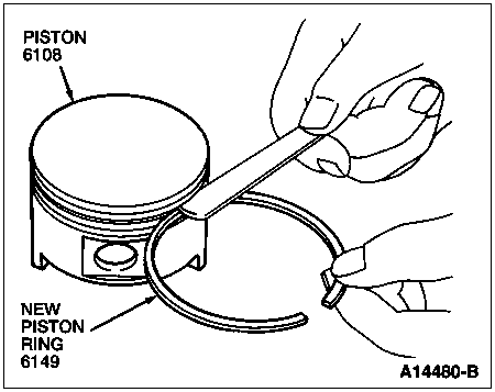
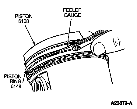
Insert each piston ring backwards (see illustration) in the piston ring groove into which it will be installed.
Measure the clearance between the ring and groove (side clearance) with a feeler gauge and check against the side clearance specifications in the appropriate Section 03-01A (4.9L SFI), Section 03-01B (5.0L and 5.8L MFI), Section 03-01C (7.5L MFI) or Section 03-01D (7.3L diesel).
Insert the ring in the cylinder bore.
Using the piston, without rings, turned upside down, press the ring down to the center of the bore.
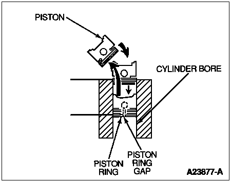
Make sure that the ring is "square" in the bore.
Piston Rind End Gap
Check the piston ring end gap specification in the appropriate Section 03-01A (4.9L SFI), Section 03-01B (5.0L and 5.8L MFI), Section 03-01C (7.5L MFI) or Section 03-01D (7.3L diesel). Using a feeler gauge, check the piston ring end gap.
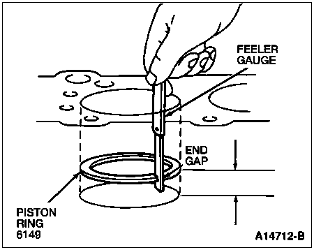
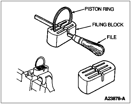
If the ring gap is too small, the ring will have to be filed until the end gap is within specifications. The use of a ring filing block helps to make sure that the ring ends are filed square.
 CAUTION: Install the piston rings after the piston has been installed on the connecting rod. Since the piston may be supported by the crown during this operation, the rings could be damaged.
 CAUTION: Use a piston ring expander to install the piston rings. Attempting to wind them on by hand may put a deep scratch in the piston or break the ring.
Using a piston ring expander, install the piston rings starting with the oil control rings. Make sure rings are installed right side up. Refer to instructions with the ring set.
Rotate the rings so the end gaps are NOT lined up but are spaced properly as shown.
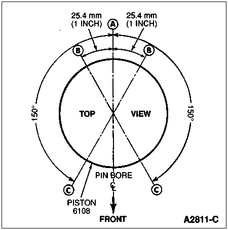
Using a feeler gauge, recheck piston ring side clearance.
Continue with engine assembly as outlined in the appropriate Section 03-01A (4.9L SFI), Section 03-01B (5.0L and 5.8L MFI), Section 03-01C (7.5L MFI) or Section 03-01D (7.3L diesel).
Piston and Piston Pin Fit
NOTE: New pistons come with fitted pins and should not require refitting unless the connecting rod bore is oversize.
The Ford 4.9L, 5.0L, 5.8L, 7.5L gasoline engines, and the 7.3L diesel engine all use piston pins that press into the connecting rod. The piston pivots on the pin. There is no connecting rod bushing and there is a friction fit between the piston pin and the connecting rod (6200).
Refer to Section 03-01A (4.9L SFI), Section 03-01B (5.0L and 5.8L MFI), Section 03-01C (7.5L MFI) or Section 03-01D (7.3L diesel), for specifications and assembly instructions.
Clean and inspect the connecting rod as outlined in Connecting Rods in this section.
Clean and inspect the piston and pin as outlined in Pistons, Piston Pins, and Piston Rings in this section.
Using a suitable micrometer, measure the piston pin both places where the piston pivots and in the center where it is pressed into the connecting rod.
Using a suitable set of plug gauges, measure the upper bore of the connecting rod. An interference fit is required. If the bore is oversize it will be necessary to install an oversize piston pin. It is not necessary to rebore or ream the connecting rod.
If the pin-to-rod fit is OK, measure the piston pin bores in the piston.
Subtract the piston pin size from the piston pin bore sizes. Pin-to-piston clearance is listed in the specifications in Section 03-01A (4.9L SFI), Section 03-01B (5.0L and 5.8L MFI), Section 03-01C (7.5L MFI) or Section 03-01D (7.3L diesel).
If clearance is excessive it will be necessary to fit an oversize pin.
To fit an oversize piston pin because either the pin-to-connecting rod or pin-to-piston clearance was excessive:
- Obtain an appropriate oversize piston pin.
- Hone or ream the piston pin bores in the piston to obtain the correct clearance.
- It is not necessary to hone or ream the connecting rod piston pin bore oversize.
Once pin, connecting rod, and piston are correctly sized to each other, assemble as outlined in Section 03-01A (4.9L SFI), Section 03-01B (5.0L and 5.8L MFI), Section 03-01C (7.5L MFI) or Section 03-01D (7.3L diesel).
Piston Pin-to-Piston Clearance
Refer to Piston and Piston Pin Fit in this section.


