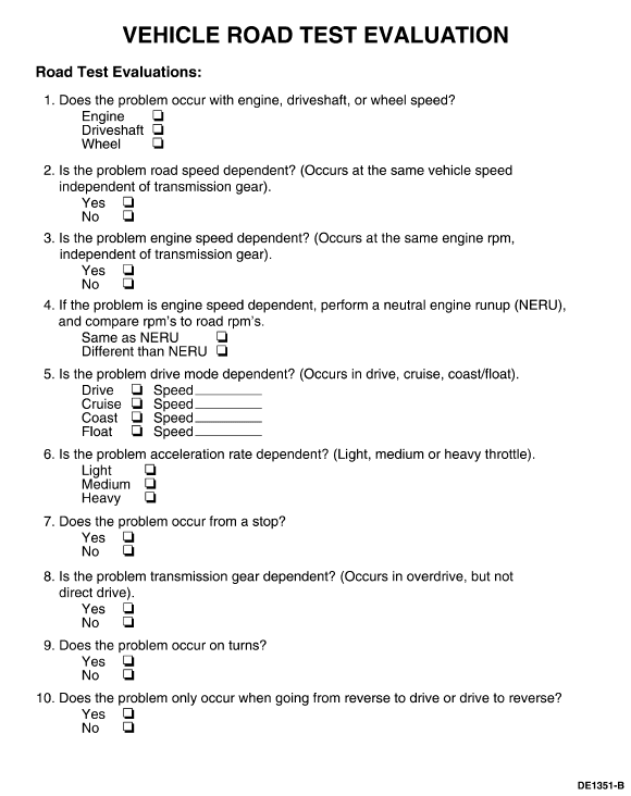
308–021 (T75L-4201–A)

100-002 (TOOL-4201-C) or equivalent

100-D002 (D78P-4201-B) or equivalent
SECTION 205-00: Driveline System — General Information | 2002 Escape Workshop Manual |
DIAGNOSIS AND TESTING | Procedure revision date: 04/29/2002 |
 | Gauge, Clutch Housing 308–021 (T75L-4201–A) |
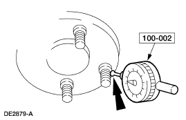
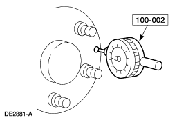
 | Dial Indicator Gauge with Holding Fixture 100-002 (TOOL-4201-C) or equivalent |
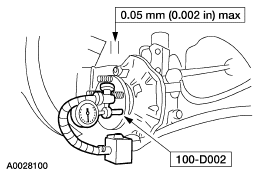
 | Dial Indicator/Gauge with Holding Fixture 100-D002 (D78P-4201-B) or equivalent |
Inspection and Verification
Certain axle and driveline trouble symptoms are also common to the engine, transmission, wheel bearings, tires, and other parts of the vehicle. For this reason, be sure that the cause of the trouble is in the axle before adjusting, repairing, or installing any new parts. Refer to Section 100-04.
Driveshaft Center Universal Joint (U-Joint) and Constant Velocity (CV) Joint Inspection
Place the vehicle on a frame hoist and rotate the driveshaft by hand. Check for rough operation or seizure of U-joints. Install a new U-joint if there are signs of seizure, excessive wear, or incorrect seating. For additional information, refer to Section 205-01. Place the vehicle on a frame hoist and rotate the driveshaft by hand. Check for rough operation or seizure of CV joint. Install a new driveshaft if it shows signs of seizure, excessive wear, or incorrect seating. For additional information, refer to Section 205-01.
Driveshaft Center Bearing
Rotate the driveshaft by hand. If the bearing shows signs of roughness or is noisy, install a new driveshaft assembly. Refer to Section 205-01.
Noise Acceptability
A gear-driven unit will produce a certain amount of noise. Some noise is acceptable and audible at certain speeds or under various driving conditions such as a newly paved blacktop road. Slight noise is not detrimental to the operation of the axle and is considered normal.
Preliminary Diagnosis
The preliminary diagnosis starts with the customer interview. The history of the concern must be investigated: When was it first noticed? Did it appear suddenly or gradually? Did any abnormal occurrence coincide with or precede its appearance (such as pothole or curb impacts, minor collisions, etc.)? Were any repair procedures carried out or new parts installed? It is also necessary to know any special conditions affecting the appearance and degree of the concern, such as road speed, type of road, drive mode, engine temperature, ambient temperature, etc.
A gradual appearance of the concern indicates a deterioration of a component, such as tires, halfshafts or wheel bearings.
A sudden appearance of the concern could indicate a lost wheel balance weight or seized CV joint.
Road Test
A road test is mandatory for any customer concern of noise/vibration that is not verified by the on-hoist check of chassis components. The Vehicle Road Test Evaluation form is arranged to record the conditions heard or felt during this test.
The road test form lists four operating conditions or modes in which some axle noises come and go: DRIVE, CRUISE, COAST, and FLOAT.
| Mode | Conditions |
|---|---|
| DRIVE | Accelerating the vehicle; a definite throttle depression applying engine torque. |
| CRUISE | Maintaining a constant speed with the throttle applied. |
| COAST | Decelerating with the throttle closed. |
| FLOAT | Controlled deceleration; backing the throttle continually to prevent either braking or accelerating torque from the engine. |
Operate the vehicle in all four modes and record those in which the noise occurs. Write down the kilometers-per-hour (miles-per-hour) range at which both noise and vibration occur. If equipped with four wheel drive (4WD), rear axle evaluations should be done on straight road sections only with 4WD lock engaged. The transfer case has similar construction to the rear differential. Both components exhibit similar noise characteristics. Axle noise can originate from either the transfer case or the rear differential. Using frequency analyzer evaluate vehicle between 60-80 mph. The transfer case will have objectionable noise frequency above 600 Hz. Rear differential will be below 600 Hz.

Analysis of Leakage
Clean up the leaking area enough to identify the exact source.
A plugged axle housing vent can cause excessive pinion seal lip wear due to internal pressure buildup.
Make sure axle lubricant level is at least 3-5 mm (1/8-3/16 inch) below the bottom of the fill hole.
Axle Vent
A plugged vent will cause excessive seal lip wear due to internal pressure buildup. If a leak occurs, check the vent. If the vent cannot be cleared, install a new vent.
Flange Yoke Seal
Leaks at the axle drive pinion seal originate for the following reasons:
Any damage to the seal bore (dings, dents, gouges, or other imperfections) will distort the seal casing and allow leakage past the outer edge of the axle drive pinion seal.
The axle drive pinion seal can be torn, cut, or gouged if it is not installed carefully. The spring that holds the axle drive pinion seal against the pinion flange may be knocked out and allow leakage past the lip.
A new pinion flange must be installed if any of these conditions exist.
Metal chips trapped at the sealing lip can cause oil leaks. These can cause a wear groove on the pinion flange and pinion seal wear.
When a seal leak occurs, install a new seal and check the vent to make sure it is clean and free of foreign material.
Drive Pinion Nut
 CAUTION: Make sure to install nut to correct torque specifications.
On some high-mileage units, oil may leak past the threads of the pinion nut. This condition can be corrected by installing a new nut and applying threadlock and sealer on the threads and nut face.
Differential Seals
 CAUTION: When installing shafts, do not allow splines to contact seal during installation.
Half shaft pilot bearing housing seals are susceptible to the same kinds of damage as axle drive pinion seals if incorrectly installed. The seal bore must be clean and the lip handled carefully to avoid cutting or tearing it. The seal journal surface must be free of nicks, gouges, and rough surface texture.
For additional information on differential seals, refer to Section 205-02.
Analysis of Vibration
Few vibration conditions are caused by the rear axle. On a vibration concern, follow the diagnosis procedure in Section 100-04 unless there is a good reason to suspect the axle.
Tires
 WARNING: Do not balance the wheels and tires while they are mounted on the vehicle. Possible tire disintegration/differential/halfshaft failure could result, causing personal injury/extensive component damage. Use an off-vehicle wheel and tire balancer only.
Most vibration in the rear end is caused by tires.
Vibration is a concern with modern, high-mileage tires if they are not "true" both radially and laterally. They are more susceptible to vibration around the limits of radial and lateral runout of the tire and wheel assembly. They also require more accurate balancing. Wheel and tire runout checks, truing and balancing are normally done before axle inspection. For additional information, refer to Section 204-04.
Wheel Hub Flange Bolt Circle Runout
NOTE: The brake discs must be removed to carry out all runout measurements.

Pilot Runout

Wheel Hub Face Runout

Wheel Hub, Steering Knuckle Inspection

Halfshafts, Rear Wheel
NOTE: Install new CV joints only if disassembly and inspection reveals unusual wear. Refer to Section 205-05.
NOTE: While inspecting the boots, watch for indentations ("dimples") in the boot convolutions. Indentations must be removed.
Component Tests
Driveline Vibration
Driveline vibration exhibits a higher frequency and lower amplitude than does high-speed shake. Driveline vibration is directly related to the speed of the vehicle and is usually noticed at various speed ranges. Driveline vibration can be perceived as a tremor in the floorpan or is heard as a rumble, hum, or boom. Driveline vibration can exist in all drive modes, but may exhibit different symptoms depending upon whether the vehicle is accelerating, decelerating, floating, or coasting. Check the driveline angles if the vibration is particularly noticeable during acceleration or deceleration, especially at lower speeds. Driveline vibration can be duplicated on a hoist. When carrying out an on-hoist test, the suspension lower arms must be supported with jack stands to make sure the halfshafts maintain the correct ride height. The brakes may need to be applied lightly in order to simulate road resistance.