CAUTION: When removing the coil-on-plugs, a slight twisting motion will break the seal and ease removal.
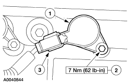
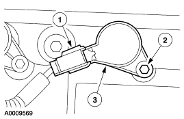
- Disconnect the electrical connectors.
- Remove the bolts.
- Remove the coils.
SECTION 303-01B: Engine Ś 3.0L (4V) | 2002 Escape Workshop Manual |
IN-VEHICLE REPAIR | Procedure revision date: 10/21/2002 |
| Item | Specification |
|---|---|
| Metal Surface Cleaner F4AZ-19A536-RA | WSE-M5B392-A |
| Silicone Brake Caliper Grease and Dielectric Compound D7AZ-19A331-A | ESE-M1C171-A |
| Silicone Gasket and Sealant F7AZ-19554-EA | WSE-M4G323-A4 |
Removal
CAUTION: When removing the coil-on-plugs, a slight twisting motion will break the seal and ease removal.
Installation
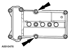
NOTE: Clean the valve cover sealing area before installing a new gasket.
Install a new valve cover gasket.NOTE: Clean the head and front cover sealing surfaces using metal surface cleaner before applying silicone gasket and sealant.
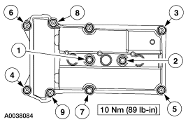
NOTE: The valve cover must be installed and the bolts tightened within four minutes of applying the sealant.
Apply a 5 mm dot of silicone gasket sealant to the front cover to cylinder head joints.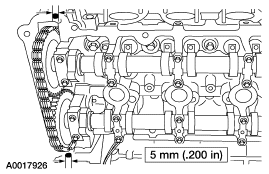
NOTE: Apply a light film of brake caliper and grease compound to the interior of the spark plug boot prior to installation.
Install the three RH coil-on-plugs.