Introduction
1996 PCED OBDI | SECTION 18: Diesel Diagnosis — 7.3L DI Engine |
AB: Injector Driver Circuit Operation Introduction | AB: Pinpoint Tests |

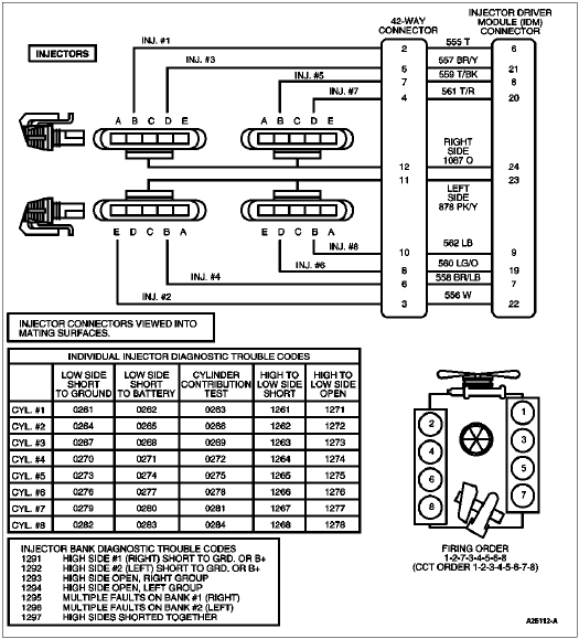
High Side Drive Outputs (Right and Left Bank) — The high side driver output function is to distribute energy to the proper bank based on cylinder identification (CID) and provide regulated current to the unit injectors, based on fuel delivery command signal (FDCS) from the injector driver module (IDM) internal 115v supply. The injection timing and duration is commanded by the powertrain control module (PCM) in the FDCS.
Low Side Drive Outputs — The low side drive outputs control the sequencing (firing order) of the engine based on the CID and FDCS inputs.
![]() WARNING: RED-STRIPED WIRES CARRY 115V DC. SEVERE ELECTRICAL SHOCK MAY BE RECEIVED. DO NOT PIERCE.
WARNING: RED-STRIPED WIRES CARRY 115V DC. SEVERE ELECTRICAL SHOCK MAY BE RECEIVED. DO NOT PIERCE.
![]() CAUTION: Do not pierce engine electrical wires or damage to the harness may occur.
CAUTION: Do not pierce engine electrical wires or damage to the harness may occur.
Detection/Management
Note: Special instructions required to clear IDM trouble codes (1995/1996 model year).
The IDM is capable of detecting individual injector open and shorts to either ground or battery while the engine is running. It is also capable of detecting right or left bank high side opens or shorts to ground. A special on-demand buzz electrical self test will also allow the operator to enable all injector solenoids while the engine is off to verify circuit operation. IDM detected trouble codes will not be transmitted if the EF line is not functioning; however, the engine will not shut down due to a non-functional EF line.
If a low side short to ground condition is determined by the IDM, this condition will be transmitted to the PCM via the EF signal. The PCM will enable the CHECK ENGINE light and command minimum fuel to the affected bank.


| IDM Pin | 42-Way Pin | Circuit | Circuit Function |
|---|---|---|---|
| 2 | 19 | 359 GY/R | SIG RTN to PCM Pin 91 |
| 4 | — | 818 (GY/W) | IDM Feedback Signal Output to PCM Pin 48 |
| 6 | 2 | 555 (T) | Low Side Fuel Injector No. 1 Pin B |
| 7 | 6 | 558 (BR/LB) | Low Side Fuel Injector No. 4 Pin B |
| 8 | 7 | 559 (T/BK) | Low Side Fuel Injector No. 5 Pin B |
| 9 | 10 | 562 (LB) | Low Side Fuel Injector No. 8 Pin B |
| 14 | — | 876 (DG/LG) | Power Input from IDM Relay |
| 16 | — | 817 (Y/LB) | Cylinder Identification Signal Input from PCM Pin 96 |
| 17 | — | 821 (BR/O) | Fuel Delivery Command Signal Input from PCM Pin 95 |
| 18 | 15 | 48 (BK) | Injector Ground Shielding |
| 19 | 8 | 560 (LG/O) | Low Side Fuel Injector No. 6 Pin D |
| 20 | 4 | 561 (T/R) | Low Side Fuel Injector No. 7 Pin D |
| 21 | 5 | 557 (BR/Y) | Low Side Fuel Injector No. 3 Pin D |
| 22 | 3 | 556 (W) | Low Side Fuel Injector No. 2 Pin D |
| 23 | 11 | 878 (PK/Y) | Left High Side Fuel Injectors Pin C |
| 24 | 12 | 1087 (O) | Right High Side Fuel Injectors Pin C |
| 26 | — | 570 (BK/W) | Ground |
After removing connectors, always check for damaged pins, corrosion, loose terminals, etc.
| Test Points | Spec. | Comments |
|---|---|---|
| B | >10,000 ohms | Injector low side |
| C | >10,000 ohms | Injector power feed, high side |
| D | >10,000 ohms | Injector low side |
| Test Points | Spec. | Comments |
|---|---|---|
| B | >10,000 ohms | Injector low side |
| C | >10,000 ohms | Injector power feed, high side (120 volts when engine is running) |
| D | >10,000 ohms | Injector low side |
| Test Points | Spec. | Comments |
|---|---|---|
| B to C | 2 to 4 ohms | Resistance through injector solenoid and UVC harness |
| C to D | 2 to 4 ohms | Resistance through injector solenoid and UVC harness |
| AB: Pinpoint Tests |